
User Guide

MPLAB
®
PICkit™ 4 USER’S GUIDE
2018 Microchip Technology Inc. DS50002751C-page 59
Appendix B. Hardware Specification
The hardware and electrical specifications of the MPLAB PICkit 4 In-Circuit Debugger
system are detailed.
These topics are covered:
• USB Connector
• MPLAB PICkit™ 4 In-Circuit Debugger
• Communication Hardware
• Target Board Considerations
B.1 USB CONNECTOR
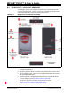
The MPLAB PICkit 4 In-Circuit Debugger is connected to the host computer via a
Micro-B USB connector, version 2.0 compliant. The Micro-B USB connector is located
on the top of the debugger.
The system is capable of reloading the firmware via the USB interface.
System power is derived from the USB interface. The debugger is classified as a high
power system per the USB specification, and requires slightly more than 50 mA of
power from the USB to function in all operational modes (debugger/programmer).
Cable Length – The computer-to-debugger cable, shipped with the debugger kit, is the
correct length for proper operation.
Powered Hubs – If you are going to use a USB hub, make sure it is self-powered. Also,
USB ports on computer keyboards do not have enough power for the debugger to
operate.
Computer Hibernate/Power-Down Modes – Disable the hibernate or other power
saver modes on your computer to ensure proper USB communications with the
debugger.
Note: The MPLAB PICkit 4 In-Circuit Debugger is powered through its Micro-B
USB connector. The target board is powered from its own supply.
Alternatively, the MPLAB PICkit 4 can power the target board only if the
target consumes less than 50 mA.