
User Guide


MPLAB
®
PICkit™ 4 User’s Guide
DS50002751C-page 28 2018 Microchip Technology Inc.
For ICE devices, an ICE header board is required. The header board contains the
hardware necessary to emulate a specific device or family of devices. For more
information on ICE headers, see the “Processor Extension Pak and Header
Specification” (DS50001292)
.
A transition socket is used with the ICE header to connect the header to the target
board. Transition sockets are available in various styles to allow a common header to
be connected to one of the supported surface mount package styles. For more
information on transition sockets, see the “Transition Socket Specification”
(DS50001194).
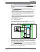
Header board layout will be different for headers or processor extension packs. For
connection information, see Section 2.2 “Debugger to Target Communication”.
3.8.3 Using an ICD Header
All Baseline and some Mid-Range PIC microcontrollers require a special –ICD device
mounted on a debug header circuit board to enable the debugging feature. For a list of
these devices and the required ICD header board part number, please see the
“Processor Extension Pak and Header Specification” (DS50001292).
Each ICD header board comes with the necessary – ICD device and is used on the
target board instead of the production microcontroller. However, most header boards
have an RJ-11 debug connector which requires the AC164110 RJ-11 to ICSP™
adapter kit to connect it to MPLAB PICkit 4.
Many Mid-Range PIC microcontrollers and all PIC18 and 16-bit PIC microcontroller
devices do not require an ICD header and can be debugged directly through the ICSP
programming connections.
3.8.4 Powering the Target
These are configuration essentials:
• When using the USB connection, MPLAB PICkit 4 can be powered from the
computer but it can only provide a limited amount of current, up to 50 mA, at V
DD
from 1.2-5V to a small target board.
• The desired method is for the target to provide V
DD since it can provide a higher
current. The additional benefit is that plug-and-play target detection facility is
inherited, i.e., MPLAB X IDE will let you know in the Output window when it has
detected the target and has detected the device.
If you have not already done so, connect the MPLAB PICkit 4 to the target using the
appropriate cables (see Section 3.7 “Connecting the Target Board”). Then power
the target.
3.9 SETTING UP MPLAB X IDE
Once the hardware is connected and powered, MPLAB X IDE may be set up for use
with the MPLAB PICkit 4 in-circuit debugger.
On some devices, you must select the communications channel in the Configuration
bits, e.g., PGC1/EMUC1 and PGD1/EMUD1. Make sure the pins selected here are the
same ones physically connected to the device.
Refer to the MPLAB X IDE Help for details on installing the software and setting up the
debugger to work with it.
Note: Headers are not supported at this time.