
User Guide

Operation
2018 Microchip Technology Inc. DS50002751C-page 19
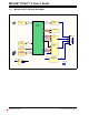
2.3.5 Circuits That Will Prevent the Debugger From Functioning
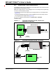
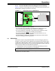
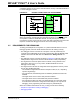
Figure 2-7 shows the active debugger lines with some components that will prevent the
MPLAB PICkit 4 debugger system from functioning.
FIGURE 2-7: IMPROPER CIRCUIT COMPONENTS
Specifically, these guidelines must be followed:
• Do not use pull-ups on PGC/PGD – they will disrupt the voltage levels, since
these lines have programmable pull-down resistors in the debugger.
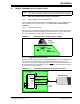
• Do not use capacitors on PGC/PGD – they will prevent fast transitions on data
and clock lines during programming and debug communications.
• Do not use capacitors on MCLR
– they will prevent fast transitions of VPP. A
simple pull-up resistor is generally sufficient.
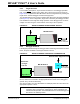
• Do not use diodes on PGC/PGD – they will prevent bidirectional communication
between the debugger and the target device.
2.4 DEBUGGING
There are two steps to using the MPLAB PICkit 4 In-Circuit Debugger system as a
debugger. The first requires that an application be programmed into the target device
(usually with the MPLAB PICkit 4 itself). The second uses the internal in-circuit debug
hardware of the target Flash device to run and test the application program. These two
steps are directly related to the MPLAB X IDE operations:
1. Programming the code into the target and activating special debug functions.
2. Debugging the code using features such as breakpoints.
If the target device cannot be programmed correctly, the MPLAB PICkit 4 In-Circuit
Debugger will not be able to debug.
No!
No!
No!
No!
VPP/MCLR
PGC
PGD
1
5
4
Interface
Connector
MPLAB PICkit 4
Note: For information on debugging, refer to the MPLAB X IDE online Help.