
User Guide

MPLAB
®
PICkit™ 4 User’s Guide
DS50002751C-page 16 2018 Microchip Technology Inc.
2.2.1 Standard ICSP™ Device Communication
The debugger system can be configured to use standard ICSP communication for both
programming and debugging functions.
Make sure to align the Pin 1 on the debugger to Pin 1 on the target. The programming
connector can be inserted into either:
• A matching connector at the target, where the target device is on the target board
(Figure 2-1).
• A standard adapter/header board combo (available as a Processor Pak), which is
then plugged into the target board (Figure 2-2).
For more on standard communication, see Section B.3.1 “Standard
Communication”.
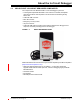
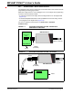
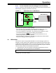
FIGURE 2-1: STANDARD DEBUGGER SYSTEM – DEVICE WITH
ON-BOARD ICE CIRCUITRY
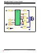
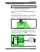
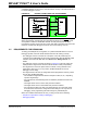
FIGURE 2-2: STANDARD DEBUGGER SYSTEM – ICE DEVICE
Target Device
or PIM
Power
MPLAB PICkit 4
Micro-B USB
cable to computer
Target Board
Header
(if needed)
Target Board
Device-ICE
AC164110
Adapter
Header
Power
MPLAB PICkit 4
Transition Socket
Micro-B USB
cable to
computer
Header
(if needed)