
User Guide

MPLAB
®
PICkit™ 4 USER’S GUIDE
2018 Microchip Technology Inc. DS50002751C-page 15
Chapter 2. Operation
2.1 INTRODUCTION
A simplified theory of operation of the MPLAB
®
PICkit™ 4 in-circuit debugger system
works is provided here. It is intended to provide enough information so a target board
can be designed that is compatible with the debugger for both debugging and
programming operations. The basic theory of in-circuit debugging and programming is
described so that problems, if encountered, are quickly resolved.
• Debugger to Target Communication
• Target Communication Connections
• Debugging
• Requirements for Debugging
• Programming
• Resources Used by the Debugger
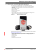
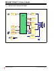
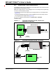
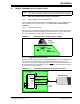
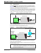
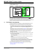
2.2 DEBUGGER TO TARGET COMMUNICATION
The debugger is connected to the computer via a USB cable for communication and
debugger power.
The debugger is connected to the target application for communication and data
collection and optional debugger power.
The debugger system configurations are discussed in the following sections.
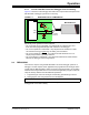
Note: The MPLAB X IDE software must be installed prior to connecting the
MPLAB PICkit 4 In-Circuit Debugger.
CAUTION
Communication Failure.
Do not connect the hardware before installing the software and
USB drivers.
CAUTION
Debugger or Target Damage.
Do not change hardware connections while the debugger or target
is powered.
Note: The MPLAB PICkit 4 in-circuit debugger is warrantied for operation using
the provided cable. Cables from other vendors may result in
communication errors.