
User Guide

MPLAB
®
PICkit™ 4 User’s Guide
DS50002751C-page 12 2018 Microchip Technology Inc.
The MPLAB PICkit 4 debugger was developed for debugging embedded processors
with rich debug facilities which differ from conventional system processors in the
following aspects:
• Processors run at maximum speeds
• Capability to incorporate I/O port data input
• Advanced host communication interfaces (Windows, macOS and Linux)
• Advanced communication mediums and protocols
• Faster programming times
• Capability to be used as a device production programmer
1.3 MPLAB PICKIT 4 IN-CIRCUIT DEBUGGER ADVANTAGES
The MPLAB PICkit 4 In-Circuit Debugger system provides the following advantages:
Features/Capabilities:
• Connects to computer via high-speed USB 2.0 (480 Mbits/s) cable
• An 8-pin SIL programming connector and the option to use various interfaces
• Programs devices using MPLAB X IDE or MPLAB IPE
• Supports multiple hardware and software breakpoints, stopwatch, and source
code file debugging
• Debugs your application on your own hardware in real time
• Sets breakpoints based on internal events
• Monitors internal file registers
• Debugs at full speed
• Configures pin drivers
• Field-upgradeable through an MPLAB X IDE firmware download
• Adds new device support and features by installing the latest version of MPLAB X
IDE (available as a free download at https://www.microchip.com/mplabx/)
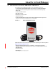
• Indicates debugger status via the indicator light strip
• Operates within a temperature range of 0-70 degrees Celsius.
Performance/Speed:
• More and faster memory
• A Real-Time Operating System (RTOS)
• No firmware download delays incurred when switching devices
• A 32-bit MCU running at 300 MHz
Safety:
• Receive feedback from debugger when external power supply is needed for target
• Supports target supply voltages from 1.2V to 5.5V
• Protection circuitries are added to the probe drivers to guard from power surges
from the target
•V
DD and VPP voltage monitors protect against overvoltage conditions/all lines
have over-current protection
• Programming/debugging pins with a programmable range of resistor values, plus
direction (pull-up, pull-down, or nonexistent).
• Controlled programming speed provides flexibility to overcome target board
design issues
• CE and RoHS compliant – conforms to industry standards