
Data Sheet


10 DOF IMU Sensor (C) User Manual
3
V1.1, Jan. 10 2017
share awesome hardware
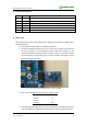
10 DOF IMU Sensor. For detail operations as below:
A. Flatting 10 DOF IMU Sensor on the horizontal position and no motion is
allowed,when serial terminal received the stable data from USART1, then press
JOYSTICK button down, LED1 is flashing and both of LED2 and LED3 turn off at the
mean time.
B. Rotating 10 DOF IMU Sensor 180 degrees around the Z axis on the horizontal
position, when serial terminal received the stable data from USART1, then press
JOYSTICK button down, LED2 is flashing and both of LED1 and LED3 turn off at the
mean time.
C. Inverting 10 DOF IMU Sensor on the horizontal position, means holding the
backside of 10 DOF IMU Sensor upward and the positive side downward. Then press
JOYSTICK button down, LED3 turn on forever indicating that magnetic calibration is
complete, and both of LED1 and LED2 turn off at the mean time.
D. Rotating 10 DOF IMU Sensor 180 degrees around the Z axis on the horizontal
position,recording and comparing with the magnetic data from serial terminal
before and after rotating, if equaling to each other and behaving at opposite of
direction, as a result, magnetic calibrating is successful.
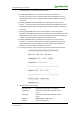
⑤ If succeed to calibrate, serial terminal will received the qualify data as following:
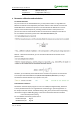
⑥ The serial output is as followed:
Roll, Pitch, Yaw
Roll angle(°), Pitch angle(°), Yaw angle(°)
Acceleration
Acceleration value (LSB, translatable into the
unit: g)
Gyroscope
Acceleration value (LSB, translatable into the
unit: g)
Magnetic
Digital compass title angle (°)
Pressure
Pressure value (hPa)