
Data Sheet

10 DOF IMU Sensor (C) User Manual
2
V1.1, Jan. 10 2017
share awesome hardware
3. Interface Descriptions
Pin No.
Symbol
Descriptions
1
VCC
3.3V or 5V power supply
2
GND
Supply ground
3
SDA
I2C serial bus data
4
SCL
I2C serial bus clock input
5
INT
MPU9255digital interrupt output
6
FSYNC
MPU9255frame synchronous signal
Table 2: Interface descriptions
4. How to use
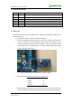
We will illustrate the usage of the module with an example of working with a STM32 series’
development board.
① Download the relative codes to the development board.
② Connect the development board to a PC via a serial wire, and insert the module into
the I2C 2 interface on the development board. Please take attention to the
connection between the module and I2C 2 interface, each pin of the module should
be connected to its corresponding port on the I2C 2 interface and FSYN pin should
be kept suspended respectively.
Figure 1: Connection between 10 DOF IMU Sensor module and STM32
③ Here is the configuration of the serial port, as Table 3 shows.
Baud rate
115200
Data bit
8
Stop bit
1
Parity bit
none
Table 3: Serial port configuration
④ After powering 10 DOF IMU Sensor on, firstly, acceleration is calibrated at horizontal
state, and magnetic is calibrated later. After done, the qualify data will output from