
Data Sheet


CP2102
Rev. 1.1 13
8. Virtual Com Port Device Drivers
The CP210x Virtual COM Port (VCP) device drivers allow a CP2102-based device to appear to the PC's
application software as an additional COM port (in addition to any existing hardware COM ports). Application
software running on the PC accesses the CP2102-based device as it would access a standard hardware COM
port. However, actual data transfer between the PC and the CP2102 device is performed over the USB. Therefore,
existing COM port applications may be used to transfer data via the USB to the CP2102-based device without
modifying the application. Contact Silicon Laboratories for the latest list of supported operating systems.
Note: Silicon Laboratories’ VCP device drivers are required for device operation and are only distributed as part of the CP2102
Evaluation Kit (Part Number: CP2102EK). Contact any of Silicon Lab’s sales representatives or go to www.silabs.com to
order the CP2102 Evaluation Kit. The CP210x drivers and programming utilities are subject to change without notice.
Subscription to the website "Auto Email Alert" system for automatic notification of updates and the use of the "Product
Update Registration" service is recommended.
9. USBXpress Direct Driver Support
The Silicon Laboratories USBXpress for CP210x Development Kit provides an alternate solution for interfacing
with CP210x devices than using the Virtual COM port. No Serial Port protocol expertise is required. Instead, a
simple, high-level application program interface (API) is used to provide simpler CP201x connectivity and
functionality.
The USBXpress for CP210x Development Kit includes Windows device drivers, Windows device driver installer
and uninstallers, and a host interface function library (host API) provided in the form of a Windows Dynamic Link
Library (DLL). The included device drivers and installation files support MS Windows 98SE/2000/XP.
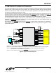
10. Voltage Regulator
The CP2102 includes an on-chip 5 to 3 V voltage regulator. This allows the CP2102 to be configured as either a
USB bus-powered device or a USB self-powered device. These configurations are shown in Figure 7 and Figure 8.
When enabled, the 3 V voltage regulator output appears on the V
DD
pin and can be used to power external 3 V
devices. See Table 8 for the voltage regulator electrical characteristics.
Alternatively, if 3 V power is supplied to the V
DD
pin, the CP2102 can function as a USB self-powered device with
the voltage regulator disabled. For this configuration, it is recommended that the REGIN input be tied to the 3 V net
to disable the voltage regulator. This configuration is shown in Figure 9.
The USB max power and power attributes descriptor must match the device power usage and configuration. See
application note “AN144: CP210x Customization Guide” for information on how to customize USB descriptors for
the CP2102.
Note: It is recommended that additional decoupling capacitance (e.g., 0.1 µF in parallel with 1.0 µF) be provided on the REGIN
input.
Table 8. Voltage Regulator Electrical Specifications
–40 to +85 °C unless otherwise specified.
Parameter Conditions Min Typ Max Units
Input Voltage Range 4.0 — 5.25 V
Output Voltage Output Current = 1 to 100 mA* 3.0 3.3 3.6 V
VBUS Detection Input Threshold 1.0 1.8 4.0 V
Bias Current — 90 — µA
*Note: The maximum regulator supply current is 100 mA.