9/24/2015 ARPI600 Waveshare Wiki ARPI600 From Waveshare Wiki Contents 1 How to start up serial debugging function 2 How to control peripherals by Raspberry Pi 2.1 System serial port configuration 2.2 Install relative libraries 2.3 Serial data display 3 Building a wireless network with two XBee modules 3.1 Preparations 3.2 Installing X‐CTU tool 3.3 Testing the connection between PC and XBee 3.4 Configuring XBee‐A module 3.
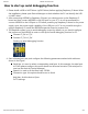
9/24/2015 ARPI600 Waveshare Wiki How to start up serial debugging function 1. Please install a USB to UART driver ﴾cp2102 driver﴿ before applying Raspberry Pi board. After the installation, please open Device Manager to check whether the PC can identify the USB to UART driver. 2. After connecting ARPI600 to Raspberry Pi board, you should power up the Raspberry Pi board and then connect ARPI600 to the USB port on your PC.
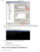
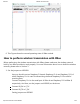
9/24/2015 ARPI600 Waveshare Wiki 5. Then, you will see a window popped up as the following figure shows ﴾If there is nothing shown in the window, please press the key Enter, then you can see the information displayed as the figure shows﴿. Connecting PuTTY to Raspberry Pi board 6. In this window, you should input following information: User name: pi Password: raspberry Then, you can enter the serial terminal. How to control peripherals by Raspberry Pi http://www.waveshare.
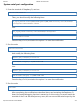
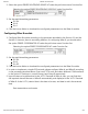
9/24/2015 ARPI600 Waveshare Wiki System serial port configuration 1. Enter the terminal of Raspberry Pi, and run: sudo nano /boot/cmdline.txt Then, you should modify the following lines: wc_otg.lpm_enable=0 console=ttyAMA0,115200 kgdboc=ttyAMA0,115200 console=tty1 root=/dev/mmcblk0p2 rootfstype=ext4 elevator=deadline rootwait into: dwc_otg.lpm_enable=0 console=tty1 root=/dev/mmcblk0p2 rootfstype=ext4 elevator=deadline rootwait Press the keys Ctrl+X, and select the option Y to save the modification.
9/24/2015 ARPI600 Waveshare Wiki software ﴾If you want to reset the serial port to the serial debugging output, please restore the factory settings and restart the Raspberry Pi. Therefore, it is recommended to backup the Raspbian before making any modification﴿. Install relative libraries 1. Copy the library file software/wiringPi.tar.gz into Raspberry Pi ﴾you can perform it by a U disk﴿, and enter the terminal of Raspberry Pi to input the following code: sudo tar xvf wiringPi.tar.
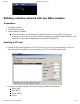
9/24/2015 ARPI600 Waveshare Wiki Building a wireless network with two XBee modules Preparations 1. Two XBee modules 2. Two ARPI600 modules 3. Twp Raspberry Pi boards In this document, we will divided the device above into two groups: Group A and Group B, of which Group A contains XBee‐A, Raspberry Pi board‐A and ARPI600‐A, and Group B contains XBee‐B Raspberry Pi board‐B and ARPI600‐B. Installing X‐CTU tool 1. Double click the file software/X‐CTU V5.2.8.6.exe on your PC to start installing X‐CTU tool.
9/24/2015 ARPI600 Waveshare Wiki Testing the connection between PC and XBee 1. Connect XBee‐A to ARPI600‐A, and XBee‐B to ARPI600‐B, respectively. 2. Set the jumpers on ARPI600 to start up the serial debugging function for the XBee, as the figure shows. Connect XB_RX to CP_RX Connect CP_TX to XB_TX Jumpers setting for serial debugging function between the Pi and the XBee 3. Power up Raspberry Pi board ﴾For more detailed information. 4.
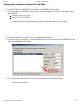
9/24/2015 ARPI600 Waveshare Wiki Configuring XBee‐A module 1. Select the option Modem Configuration, and click the button Read to read out the current parameters of XBee. Reading out current parameters http://www.waveshare.
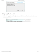
/24/2015 ARPI600 Waveshare Wiki 2. Select the option ZIBGEE ROUTER/END DEVICE AT under the pull‐down menu Function Set: Selecting the option ZIBGEE ROUTER/END DEVICE AT under Function Set 3. Set the read Networking parameters: ID: 234 DH: 0 DL: 0 4. Click the button Write to download the configured parameters into the XBee‐A module. Configuring XBee‐B module 1. Configure XBee‐B module according to the processes described in the Section 3.1 and the Section 0. However, there is something different.
9/24/2015 ARPI600 Waveshare Wiki 6. This Figure shows the normal operating state of XBee module. How to perform wireless transmission with XBee Before performing the wireless transmission with XBee, please make sure the wireless network built by two XBee modules is work properly. For more information about how to build the wireless network, please refer to Section 3. 1.
9/24/2015 ARPI600 Waveshare Wiki 2. Testing the serial port: Copy the file program/Xbee/getdata to the Raspberry Pi‐B, and enter the folder getdata. Then, execute the code: sudo make sudo ./serialTest The relative data will be displayed as followed. Displaying the message getdata 3. Run the code for transmitting data on Raspberry Pi‐A. Then, copy program/Xbee/send into the Raspbian, and enter the folder send to execute the following code: sudo make sudo .
9/24/2015 ARPI600 Waveshare Wiki 4. Enter LXTerminal, and run: modprobei2c‐dev echo pcf8563 0x51 > /sys/class/i2c‐adapter/i2c‐1/new_device hwclock –r ﴾Read out the time of the connected RTC based on I2C﴿ LXTerminal will display the time clocked by PCF8563 which may be different from the Raspbian﴿ 5.
9/24/2015 ARPI600 Waveshare Wiki Notices: REF can only be connected to one reference voltage at a time. Setting AD reference voltage 3. Copy the file program/AD_TLC1543 in to Raspbian. Then, enter the folder AD_TLC1543, and execute the following code under the terminal: sudo make sudo ./tlc1543 4. Terminal will display relative AD conversion value. By default, the displayed conversion value is come from Pin AD0 on TLC1543 ﴾Pin T_A0 on ARPI600﴿. 5.
9/24/2015 ARPI600 Waveshare Wiki example, modify to “1” for testing the conversion value from Pin AD1 ﴾Pin T_A1﴿, and modify to “2” for testing the conversion value from Pin AD2 ﴾Pin T_A2﴿, and so on, until to “10” for testing the conversion value from Pin AD10 ﴾T_A10﴿﴿. After completing the operation described above, press the keys Ctrl+X, and select the option Y to save the modification. 2. Execute the following code under the terminal: sudo make sudo ./tlc1543 Now, the modification is in effect.
9/24/2015 ARPI600 Waveshare Wiki Configuring the jumpers D11, D12 and D13 In factory settings, the jumpers are set as followed: Connect SCK to D13 Connect MISO to D12 Connect MOSI to D11 The following settings are connecting pins D11, D12 and D13 to the general IO control pins of Raspberry Pi board. Connect D13 to P26 Connect D12 to IO_SD Connect D11 to IO_SC Notices: Users can modify the settings of these jumpers as required. In this operation, welding is required.
9/24/2015 ARPI600 Waveshare Wiki APRI600 IO of Raspberry Pi B+ A0 CE1 A1 P21 A2 P22 A3 P23 A4 P24 A5 P25 b﴿ When the pins A0‐A5 are connected to 3, they will sever as ADC pins. You can also connect the pin A4 to P_SCL, and the pin A5 to P_SDA ﴾as the figure shows﴿, to making them sever as I2C control pins of Raspberry Pi board. However, in default settings, the pins A4 and P_SCL are disconnected, and so do the pins A5 and P_SDA.
9/24/2015 ARPI600 Waveshare Wiki Resources Introduction ﴾http://www.waveshare.com/ARPI600.htm﴿ Schematic ﴾http://www.waveshare.com/w/upload/0/06/ARPI600‐Schematic.pdf﴿ Code ﴾http://www.waveshare.com/w/upload/9/9f/ARPI600‐Code.zip﴿ Application Notes CP2102 PCF8563 Writing the Img to the SD card ﴾http://www.waveshare.com/w/upload/4/49/Writing‐the‐ Img‐to‐the‐SD‐card.pdf﴿ Libraries Installation for RPi Datasheets TLC1543 Datasheet CP2102 PCF8563 Software Panasonic_SDFormatter ﴾http://www.waveshare.
9/24/2015 ARPI600 Waveshare Wiki Categories: Expansions Raspberry Pi Arduino This page was last modified on 7 August 2015, at 16:21. This page has been accessed 2,356 times. http://www.waveshare.