WAVES Kramer PIE Compressor User Guide
TABLE OF CONTENTS CHAPTER 1 – INTRODUCTION ..............................................................................................................3 1.1 WELCOME .........................................................................................................................................3 1.2 PRODUCT OVERVIEW ........................................................................................................................3 1.3 ABOUT THE MODELING .......................................
Chapter 1 – Introduction 1.1 Welcome Thank you for choosing Waves! In order to get the most out of your new Waves plugin, please take a moment to read this user guide. To install software and manage your licenses, you need to have a free Waves account. Sign up at www.waves.com. With a Waves account you can keep track of your products, renew your Waves Update Plan, participate in bonus programs, and keep up to date with important information.
These are some of the most important elements of analog behavior: • Total Harmonic Distortion Perhaps the most important analog behavior is Total Harmonic Distortion or THD, which is defined as the ratio of the sum of the powers of all harmonic components to the power of the fundamental frequency. THD is usually caused by amplification, and changes signal shape and content by adding odd and even harmonics of the fundamental frequencies, which can change the overall tonal balance.
Chapter 2 – Quickstart Guide The Kramer PIE offers 3 main compression controls: • Use the Threshold control to control the level at which the compressor activates, beginning attenuation. Watch the VU meter needle to determine when attenuation begins, and adjust your settings accordingly. • Use the Compression Ratio control to set the amount of gain change that will be applied to signal overshooting the threshold.
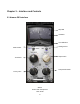
Chapter 3 – Interface and Controls 3.
3.2 Kramer PIE Controls Threshold sets the gain reference point beyond which compression begins. Range -24 to +16 dB (in 2 dB steps) Default +16 Ratio controls the amount of gain reduction for signal above the threshold.
Decay Time (Release Time) sets the recovery speed of the gain attenuation when the input drops below the threshold. Range 1, 2, 4, 8, 16, 32 (hundredths of milliseconds) Default 4 Output sets the output level. Range -18 to +18dB.
Meter Select toggles between Input, Output, and Gain Reduction metering. Range Input, Output, Gain Reduction Default Gain Reduction Analog controls analog characteristics caused by noise floor and hum, based on the power supplies of the original units. Range 50 Hz, 60 Hz, Off Default 50 Hz VU Meter displays input or output level in dBVU and gain reduction with smooth analog modeled ballistics. Please note: The PIE Stereo component meter displays the sum of both channels.
Clip LED lights up when levels exceed 0 dBFS. Click to reset. VU Calibrate controls the VU meter headroom calibration. Range 24 – 8dB Default 18 dB of headroom (0 dBVU = -18 dBFS) Please note: The VU Calibration control is represented by the little screw-head right below the VU meter display. It does not have a visible label and, for most users, the 18 dB default headroom should be the best choice.