WAVES Kramer HLS Channel User Guide
TABLE OF CONTENTS CHAPTER 1 – INTRODUCTION ..............................................................................................................3 1.1 WELCOME .........................................................................................................................................3 1.2 ABOUT KRAMER HLS CHANNEL .........................................................................................................3 1.3 ABOUT THE MODELING ..............................................
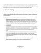
Chapter 1 – Introduction 1.1 Welcome Thank you for choosing Waves! In order to get the most out of your new Waves plugin, please take a moment to read this user guide. To install software and manage your licenses, you need to have a free Waves account. Sign up at www.waves.com. With a Waves account you can keep track of your products, renew your Waves Update Plan, participate in bonus programs, and keep up to date with important information.
we were able to model original channels that were in the truck from 1970 – 1973, when the console was redone by Helios according to specs from engineer Mick McKenna. Our long, arduous search for the perfect Olympic-style channel reflects the rarity of the original units, and we are truly excited and proud to present the Helios sound for posterity, and for the creative use of generations to come. 1.
1.4 Components WaveShell technology enables us to split Waves processors into smaller plug-ins, which we call components. Having a choice of components for a particular processor gives you the flexibility to choose the configuration best suited to your material.
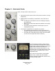
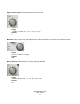
Chapter 2 – Quickstart Guide At left: The EQ section of the Kramer HLS. • High frequency EQ: Grab and turn the top knob to boost or cut high frequencies. • Midrange EQ is controlled by a combination of two knobs and a switch: o The Mid gain knob sets the amount of midrange frequency gain adjustment. o Below it is the switch that determines whether to boost (PK) or cut (TR). o The knob to the left selects the center frequency of the midrange EQ (in kHz).
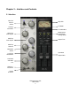
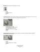
Chapter 3 – Interface and Controls 3.1 Interface Mic/Line Source Select Clip LED VU Meter Preamp Coloration VU Calibration Meter Select Noise Mode Analog Switch .
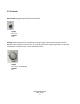
3.2 Controls Source Select toggles between Mic and Line levels. Range Mic, Line Default Line Preamp determines the amount of preamp coloration. Higher values introduce more harmonic distortion with increased noise and hum. The overall level will not change significantly, as the HLS recreates the coloration alone, not the amplification itself.
High Frequency Gain controls high shelf gain at 10 kHz. Range -16 dB to +12 dB (-16, -12, -8, -4, 0, 4, 8, 12) Default 0 Mid Gain sets the amount of gain applied to the midrange bell filter, according to the selected mode. Range 0 to 15 (15 dB in 0.1 steps) Default 0dB Mid Frequency selects frequency for the midrange bell filter. Range 700 Hz to 6 kHz (700, 1, 1.4, 2, 2.8, 3.5, 4.5, 6) Default 2.
Mid Mode selects between boost (PK) and cut (TR). Range PK (boost), TR (cut) Default PK Low Band Freq/Cut From 60 to 400, this knob is used to select the boost frequency. From 3 to 15, it is used to select the amount of attenuation (in dB) of the 50 Hz low shelf.
EQ Cut turns the EQ on (in) and off (cut), while maintaining the analog and preamp characteristics. Range: In/Cut Default: In Phase Invert reverses the phase of the signal in the plugin Range: Invert off or on Default: Off Analog controls turns the analog noise and hum modeling on and off, and sets the pitch of the hum to match either European or American currents. To retain only the modeled harmonic distortion, bypass the noise and hum by setting Analog to Off.
Meter toggles the meter display between input and output monitoring. Clip LED lights up when levels exceed 0 dBFS. Click to reset. VU Meter displays input or output level in dBVU. Please note: The HLS Stereo component meter displays the sum of both channels. The same signal fed to both channels will show an increase of 6 dB. If this is problematic, use the VU Calibration function to compensate. Range 24 – 8 dB Default 18 dB of headroom (0 dBVU = -18 dBFS.
Trim displays the maximum peak level of the output signal and its distance from 0 dBFS. Clicking on the trim value button will reset it to 0, and apply the differential to the output trim (up to 12 dB at a time.) Range -12 – +12 dB Default 0 Input controls the input level. Output controls the output level. Range -18 dB to +18 dB (in 0.1dB steps) Default 0 dB 3.3 WaveSystem Toolbar Use the bar at the top of the plugin to save and load presets, compare settings, undo and redo steps, and resize the plugin.