Waves Parametric Convolution Reverb IR-1, IR-L and IR-360 User’s Guide Waves IR-1 software guide page 1 of 40
TABLE OF CONTENTS Overview Synthetic Digital Reverberation Sampled-Acoustics Convolution Reverberation The Perfect Hybrid The Impulse Responses IR Library Factory Presets Sampled Acoustics V2 Virtual Acoustics - Devices and Synthetic Import Impulse Response from File… Import Sweep Response from File… Tips for Sampling an Acoustic Space MEASURING VINTAGE PLATES, SPRING REVERBS OR ANY REVERB UNIT MEASURING HALLS, ROOMS IR-series plug-in channel components About the IR-360: IR-series Controls and Displays Abou
LF damping Reverb EQ ER Buildup ER/TR-X Crossover IR-360 Controls Toolbar WaveSystem Controls Loading Impulse Responses Saving Importing Impulse Responses IR Info and Properties Notes on “Flat Points” or Unity Gain Settings for Controls System Requirements Notes CPU about Optimization IR-1 HTDM Waves IR-1 software guide page 3 of 40
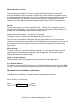
Introduction The Waves IR-1, IR-L and IR-360 plug-ins create extremely high quality replicas of acoustical spaces and synthetic reverbs. They also allow the user to alter many aspects of the sound of these reverbs. For the purpose of this Manual, when discussing attributes shared by the Waves IR-1, IR-L and IR-360 Parametric Convolution Reverb plug-ins, we will simply refer to them all as the IR-series. Overview The Waves IR-series are convolution-based reverb processors.
Sampled-Acoustics Convolution Reverberation In math, the term convolution means an integral which expresses the amount of overlap of one function x as it is shifted over another function y. In the literal sense, it means to “roll together” or to “fold together”. A convolution reverb blends together an input signal with another type of audio signal called an impulse response. Sampled-acoustics convolution processors are a different type of digital reverb than the digital reverbs that preceded them.
The Impulse Responses Another major part of the IR-series is the Impulse Response (IR) Library. The library offers a set of high-definition IR’s. Waves paid special attention to this part of the product because it is the basic reverb sound of the IR-series reverbs. We established a special recording setup and method specifically for IR recording. This method provides exceptional signal-to-noise ratio, very low harmonic distortion, and a wide frequency bandwidth (20Hz-32kHz).
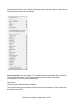
Accessing these IRs is easy. Select the desired preset from the plug-in’s “Load” button, which will present the menu as follows: Factory Presets is the first section. It is available with the installation of the IR-series, even for demo purposes. The IR data for these presets resides in the folder "IR1Impulses V2" in a directory called Basic. The Path is: Waves Plug-Ins dir/IR1Impulses V2/Basic. The Custom Setup group contains presets that only have settings. These presets can be loaded onto any IR.
Sampled Acoustics V2 The presets in this section are based on samples of real places. The contents of the Sampled Acoustics V2 folder on the DVD have to be copied into the IR1Impulses V2 folder inside the Waves Plug-Ins folder. You can add or delete folders from this directory. Each time upon loading, the Plug-In will scan the directory and dynamically build its preset menu according to the folder hierarchy.
Tips for Sampling an Acoustic Space When sampling an acoustic space, a typical setup includes a multi-track recorder, an amplifier and speaker to play the sweep signal into the space, and one or more microphones (and mic preamplifier(s), if needed) to capture the sound. Ideally, the speaker, amplifier, microphone(s), and microphone preamplifier(s) used should be as transparent as possible, having flat frequency responses.
MEASURING HALLS, ROOMS The measuring procedure of a venue is slightly different than that of measuring devices. Measuring venues requires a larger setup, which includes a playback device, a microphone and a loudspeaker. We can use the same session we were using for the device recordings, only instead, we connect the output of our playback device to a speaker, and a microphone should be assigned to the input of our recording device.
Mono to Stereo: 2 convolutions: 1 left, 1 right. Convolution Left Output Convolution Right Output Mono Input Efficient Stereo: 2 convolutions: Left in to Left out and Right In to Right Out. This component does multi-mono processing. • With Efficient Stereo, the added control for input channel Crosstalk can keep the channels separate, or sum the wet path input. This component is very practical for stereo-to-stereo reverberation.
About the IR-360: The IR-360 is the surround sound version of the IR-1. The IR-360 is HTDM for Pro Tools TDM Users. IR-360 owners will also receive an IR-1 included in the purchase.
Waves IR-1 software guide page 13 of 40
Waves IR-1 software guide page 14 of 40
Waves IR-1 software guide page 15 of 40
IR-SERIES CONTROLS AND DISPLAYS The IR-series has a large main window with controls similar to those of a standard digital reverb. Most of the values are displayed as a ratio of the nominal value of the original IR. The IR-360 has the most adjustable parameters, followed by the IR-1 and then the IR-L. About the IR-L The IR-L is essentially an IR-1 with fewer adjustable parameters. It has the same high sound quality as the IR-1. The IR-L can be upgraded at any time to an IR-1 or IR-360.
Reverb Time The Reverb Time section includes these 4 parameters: CONVOLUTION START: Range: 0 TO 1 second; Default: 0 seconds The Convolution Start determines the starting point of the convolution process. It enables you to remove unwanted pre-delay at the beginning of an IR. CONVOLUTION LENGTH: Range: 0 seconds to 6 seconds; Default: Full This control sets the length of the process filter. By default it is set to Full, which means that the IR-L will convolve the input with the whole Impulse Response.
DRY/WET CONTROL: Range: 0 to 100% wet; Default: 100% wet This control sets the balance between the “Dry” signal and the convolved signal. A 50% Wet setting is the “natural” balance point. The IR-series lets you work either with the recorded Direct signal, or with the Dry signal (that is, the unprocessed input to IR-1). When the Direct signal is turned off, and Dry/Wet is set to 50%, the Dry signal will have the same level and relative delay as the recorded Direct signal, so the Dry will replace the Direct.
DRY: Range: 0-30ms; Default: 0ms When working as an insert, the Dry latency control can be used to align the dry signal to the wet signal or even to advance it ahead. CPU MODE: Range: Full CPU or Low CPU. Default: Full CPU This control allows you to select between Full CPU (Central Processing Unit) or Low CPU. Low CPU presents an option to slightly compromise the resolution of the convolution process while saving up to 45% of the CPU cycles (depending on the IR length and Sample rate).
IR-1 AND IR-360 CONTROLS AND DISPLAYS (IR-L users can skip this section and resume reading at Toolbar Wavesystem Controls on page 30) THE IR GRAPH The IR graph shows dB level on the vertical axis and time on the horizontal axis. The range of the IR display is from 0dB at the top to –90dB at the bottom. The display incorporates an envelope curve (in orange). The scaling of the envelope curve is different: its flat bypass point is two-thirds of the graph’s height and its range is from +30dB to –60dB.
Reverb Time The Reverb Time section includes these 4 parameters: CONVOLUTION START: Range: 0 TO 1 second; Default: 0 seconds The Convolution Start control determines the starting point of the convolution process. It enables you to remove unwanted pre-delay at the beginning of an IR. CONVOLUTION LENGTH: Range: 0 seconds to 6 seconds; Default: Full This control sets the length of the process filter.
The RT60 display is active only when RT60 may be computed on the IR. There is a minimum IR length (about 100 ms) for computing RT60 as well as for activating the reverb time ratio. Reverb Control Parameters SIZE: Range: .25 to 4.00; Default: 1.00 The Size is a ratio of the original IR, and controls the dimensions and volume of the actual room. This defines the traveling time of sound between reflections. The Size value will be indicated in the IR Properties display. REVERB DENSITY: Range: 0.25 to 4.
DRY/WET CONTROL: Range: 0 to 100% Wet; Default: 100% Wet This sets the balance between the “Dry” signal and the convolved signal. 50% Wet setting is the “natural” balance point. The IR-series lets you work either with the recorded Direct signal, or with the Dry signal (that is, the unprocessed input to IR-1).
DIRECT SIGNAL Please Note: The Direct signal is not the dry signal! The dry signal is the input signal to the plug-in. The Direct signal is the direct arrival of the sound source to the listener, traveling the shortest straight-line path between them. The Direct signal is the signal that was directly emitted from the speaker and recorded by the microphone. It is the input signal convolved with the first reflection in the IR.
Sometimes shutting off the ERs or reducing their level vs. the tail level will leave a lot of reverb, but will sound less distant so that the signal sounds close and wet. You can also apply different Predelay values to the ERs and Tail. Note that the division is implemented by crossfade, so sliding the ER Predelay only slightly will produce some comb filtering in the part that overlaps with the tail reflections.
TAIL: Range: On/Off; Default: On Tail switches the reverb tail on or off. Tail Gain: Range: 0.0dB To Off; Default 0.0dB Tail Gain controls the level of the reverb tail. TAIL PREDELAY: Range: -100ms to 500ms; Default: 0.0ms This controls the amount of time that the reverb tail is delayed. The Tail Predelay can be used to make the reverb Predelay longer but it is always in addition to the inherent process latency and to any Predelay embedded into the original IR file.
CPU MODE: Range: Full CPU or Low CPU; Default: Full CPU This control allows you to select between Full CPU and Low CPU. Low CPU presents an option to slightly compromise the resolution of the convolution process and saves up to 45% of the CPU cycles depending on the IR length and Sample rate. The Average savings is about 20%. REVERSE: Range: ON/OFF; Default: Off. This will simply reverse the convolution filter to create true reverse reverbs.
Offline Calculation Indicator Manipulating the impulse response to reflect the controls settings requires recalculation of the whole impulse response. This calculation process can take up to several seconds. While the impulse response calculation is taking place, the reverb envelope graph displays “Calculating…” and the audio is muted. After the calculations are performed, the graphs are updated and the audio un-mutes. ENVELOPE BYPASS: Range: ON/OFF. Default: Off.
LOW FREQUENCY DAMPING RATIO: Range: 0.10 to 2.00; Default: 1.00 This control defines the ratio by which the frequencies below the Low Damping Frequency will decay in relation to IR’s general Reverb Time. Values of less than 1.00 are shorter than the IR’s Reverb Time, and values greater than 1.00 are longer than the IR’s Reverb Time. LOW DAMPING FREQUENCY: Range: 16Hz to 1600Hz; Default: 600Hz This defines the frequency below which the Reverb time is controlled by the Low Damping Ratio Control.
LF damping is the reduction of reverberation time at low frequencies, due to low frequency transmission in the walls. Most rooms with solid walls have little low frequency damping. In general, the reason for this is that a wall with more LF transmission has a greater level of “noise nuisance” caused by bass sounds leaking out of the room and outside bass sounds leaking into the room.
HIGH SHELF FILTER • Gain: Range –24dB to +12dB; Default: 0 • Frequency Range: 1000Hz to 21000Hz; Default: 5005 Hz • Q: Range: 0.71 to 1.41; Default: 1 OUTPUT GAIN: 0dB to –50dB; Default: 0dB The Output Gain controls the overall output level of the IR-1. ER BUILDUP: Range: 0 to 150ms; Default: 0ms The Early Reflections Buildup allows control of the buildup slope of the early reflections. It determines a transient (abrupt) or smooth attack for the early reflections.
In natural IRs, there is no distinct delineation between ER and TR; the definition of where the best ER/TR-X crossover point is subjective. The user is allowed to modify the automatic decision of the plug-in by using the ER/TR-X control, in milliseconds, relative to the automatic crossover point. In IRs where the direct signal is not found, the Direct Gain and Predelay become disabled.
IR-360 Controls: These Controls are exclusive to the IR-360: FRONT/REAR BALANCE: Range: Front to Rear; Default 50.0 The Front/Rear Balance control determines how much of the reverb is going to the front vs. the rear speakers. For instance, if the control is set to 65, then 65% of the Reverb will be put in the front speakers and 35% will be put in the rear speakers. PRE-DELAY OFFSET: Range: 0 to 80ms; Default: 0 This control adds a time delay to the reverb on the rear speakers.
Loading Impulse Responses The IR-1 load menu is the same load menu used in all WaveSystem plug-ins. Use “Open preset file…” to load a Waves setup file *.xps. Use “Import Impulse Response from WAV...” to import IR’s either from standard .wav files or from Waves Impulse Response (.wir) files. Under “Factory Presets” you can select “IR-1 Full Reset…” to load the default IR, “Hall 1”, by choosing “Impulse Response and Reset”. This loads the IR and resets all plug-in settings to the factory defaults.
The next three factory presets: Room – 1, Studio – 1, and Plate – 1 are from the Waves basic IR library. This IR Library is available with any install of the IR-1 plug-in. Most Factory Presets offer two load options: • • Impulse Response and Reset Impulse Response The first option will load the IR and reset all parameters to their default state. The latter will load the selected preset’s IR into the current setup, automatically applying the current parameters to the newly loaded IR.
You can import IRs in .wav and .wir formats (supported bit-depths: 16, 24 and 32floating point, with sample rates between 44.1kHz and192kHz). The plug-in will automatically sample-rate convert the IR to the sample rate you are working in (session sample rate is 96kHz maximum). Note: an imported .wav is not saved. If you want to move your session to another system, you will need to include in your backup any IRs and .wav(s) you need for the session.
• • • • • • • • • • • • Name – Name of the location. Type – Location type i.e. Concert Hall, Theatre, Opera House, etc. Date – Date the location was measured. SR – Sample rate of the IR and the sample rate of session you are working in. Country – Country of the sampled location. City – City of the sampled location. Emitter type – Playback loudspeaker used in the measurement of the location. Receiver Type – Microphone used in the measurement of the location.
• For Reverb controls having a ratio scale of 0.25 to 4 (Reverb Time, Density, Resonance, Size) the flat point is 1. • For Reverb controls having a percentage scale of 0% to 100% (Decorrelation, Crosstalk, Dry/Wet), the flat point is 0%. • Predelay reverb controls (Direct Predelay, ER Predelay, Tail Predelay, ER/TR-X, Dry latency) have a flat point of 0. • Flat point for Direct/ER/Tail gains and switches is 0dB with all switches “On”. • For Full-CPU/Low-CPU, the flat point is Full-CPU.
Here are a few points to use in order to increase performance, sorted by priority: BUFFER SIZE: This doesn't compromise any aspect of audio quality. Thus it is the first place the user should try to optimize system performance. A buffer of 512 is optimal. Lower buffer sizes will increase the peak CPU consumption. Higher Buffer sizes may reduce the average CPU consumption, but the peaks will be similar. Beware that not all hosts have friendly default buffer settings.
sounds like the rich reverb that it is, and it is a “mix-friendly” optimization. It is important to distinguish between Reverb Time RT60 and Convolution length. The ear is more sensitive to the slope at the higher gains, so while shortening RT60 will sound like a smaller reverb, shortening the Convolution length will simply sound less linear at the lower IR gains.