
User`s guide


Functional Overview
MS-4900, Rev. A 5–9
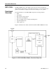
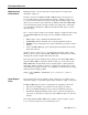
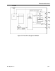
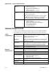
Signal Input:
LNB and Tuner
The IDR V1000 connects to the LNB on the satellite dish through the coaxial cable
attached to the rear panel RF connector. The LNB (low noise block converter)
receives power from the receiver, maps satellite signals to a pre-determined range of
frequencies (950 to 1525 MHz) and sends the appropriate commands to the tuner.
The tuner selects the specific signals (out of many delivered by the LNB) that
contain the desired aggregate data stream.
The coaxial cable needs to meet certain specifications so that interference from
nearby electrical equipment does not affect the signal before it reaches the receiver.
(The recommended coaxial cable is RG-6, not to exceed 152 meters, or 500 feet
between LNB and receiver). Line amplifiers can be added to help boost the signal if
necessary.
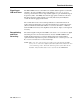
Demodulating
and Error-
Correcting
The selected signal coming from the LNB is demodulated, or re-converted to digital
data. Reception errors are then detected and corrected. All IDR V1000 models
include Viterbi forward error correction; the Reed-Solomon model includes a
separate hardware chip that incorporates an additional error correction process—the
Reed-Solomon forward error correction technique.
NOTE: This corrects reception errors across the aggregate data stream. This
level of error correction is different from the software Reed-Solomon error
correction that operates only in the stat mux portion of the data stream
and then only if stat mux data is selected for use by the IDR V1000.