
User`s guide


Interpreting Screen Displays
4–8 MS-4900, Rev. A
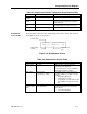
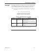
Table 4-8. Setup of Serial Ports
Field Should be: Meaning:
Port Mode • PAD or NODE
• DF
• PD/ND
• Mode
• Default destination; data addressed
to DF ports will go to this receiver
• Data addressed to PAD ports will
go to this receiver; data addressed
to Node ports will go to this
receiver
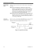
Port
configuration
• Baud rate (see Note)
• Bits per word
• Parity
• Stop bits (see Note)
• Flow control
NOTE: These communications settings
must match the communication
settings of the attached
terminal.
NOTE: For baud rates 57600 and 115200, “1 stop bit” operation is required.
Also, the serial ports will not accept data input, so XON/XOFF flow control
will not operate.
TDD channels
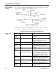
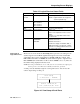
This screen within the View Setup topic shows the assigned TDM channels to each
TDD output path in the receiver. This identifies which head-end feed is delivered to
each port.
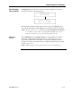
Figure 4-7. Display Based on TDM Channel Assignment
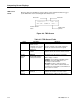
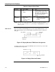
A variation of this screen occurs when TDM allocations are based on product, rather
than TDM channel assignments.
Figure 4-8. Display Based on Product
CPU:CH3 Type:L1
Ser4:Choff Ser5:Ch2
Data type
to CPU
CPU partition
Synchronous
serial ports
CPU: 3 Type: L1
Ser4: Off Ser5: 2
Product 3
Product 2