
User`s guide

Installing the IDR V1000
MS-4900, Rev. A 2-3
Step 2:
Verify
Initial Lock
On Carrier
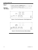
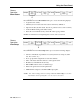
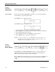
As soon as power is supplied to the IDR V1000, an automatic self-test runs. The IDR
V1000 then locates and “locks” onto the preset frequency. When this completes
successfully, the following identification screen appears (Figure 2-3).
Figure 2-3. WavePhore Identification Screen
If you do not see the identification screen within two minutes of powering on, or if you
see a character other than the “L”after a minute or two of the screen being displayed,
refer to Section 4 to troubleshoot the cause.
Step 3:
Check
E
b
/N
0
and
AGC
Readings
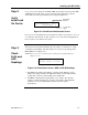
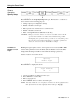
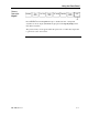
After the receiver has achieved initial lock on the carrier, you should try to “peak,”
or maximize both the E
b
/N
0
and AGC numbers. You can see both readings in the
Show Status screen (Figure 2-4).
NOTE: Refer to Section 3 for instructions on using the front panel buttons to
display screens.
Figure 2-4. Show Status Screen: AGC and E
b
/N
0
Readings
1. The AGC level indicates that cabling is complete and the LNB is powered.
Ideally, the reading should be near 200. If the number is under 100, check the
coaxial cable connections and the LNB on the satellite dish.
2. The E
b
/N
0
reading indicates signal quality; it is possible to fine tune that
reading by slightly adjusting the positioning of the satellite dish. The E
b
/N
0
should be at least 5.0, usually higher. (The site will have specific
requirements.)
©1997 WavePhore 1236
00:00 S/N:xxxxxxxx L
IDR V1000
Model #
L = locked on
signal
LOCKED table:xxxxxx
AGC:XXX Eb/No: X.X dB