
Install Guide

www.wavelynxtech.com | 100 Technology Drive, Suite 130B, Broomfield CO, 80021 | 720-572-4963
G-310-0 Fusion Install Guide May 2020, Rev 1.0
- In the case of both DC power and PoE, the Fusion IP Reader will draw power from the DC power
source.
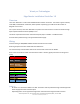
Lock Control
Magnetic Lock or Door Strike is controlled through the Switched Ground.
Switched Ground
Switched Ground enables the Ground (powering the lock) or disables ground (releasing power from the
lock). Fusion can source up to 500 mA of current through its 12V Out.
Connect the positive side of the lock to the 12V Out and Ground wire of the lock to the SW GND of the
IP Reader.
Configure the default power as either Power-On or Default Power-Off through the software.
Additionally, the Switched Ground can be utilized as an input to a PIR sensor.
+12V Trigger
Some locks require power and then a trigger to lock/unlock. For these use cases, the lock should be
powered with the Red and Black wires from the Fusion IP Reader. The Brown Wire is then connected to
the trigger line. Fusion should then be configured to have the Door Control line to +12V Trigger, in
which case the Brown line will toggle between floating and then pulled high to +12V.
Note that the +12V trigger value is pulled high with a 300 ohm resistor and is not meant to be used as an
additional 12V power source.
Reader
Communication to an external reader is performed through OSDP.
The Fusion IP Reader can communicate to external readers connected through 1,000 ft of twisted pair,
24 AWG wire at 9600 Baud.
The Fusion IP Reader was tested by UL with the Ethos Reader Line.
Total Output Power
When powered from PoE the Fusion IP Reader supplies a total of 650mA of current at 12VDC.
Inputs
Connect the door switch monitor to the DSM connector.
Connect the request to exit monitor to the REX connector
If there is an additional Input monitor, connect it to the AUX.
Reader Mounting
- Screw wallplate onto wall along with large center hole for wiring
- Wire the pigtail following wiring instructions and secure pigtail securely to backplate of the reader
using screws attached to the pigtail
- Attach RJ45 cable