
User's Manual


- 13 -
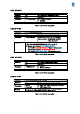
3.2.1 AT+I
Function Module information output
Example TX AT+I<Index>[Enter]
Example RX <Information>[Enter]
Parameter <Index> 0 : Product Name
1 : Firmware Version
2 : Module MAC Address
Remark
Table 5. AT+I description
3.2.2 AT+F
Function Module frequency band setting
Example TX AT+F<Space><Fstart><Space><Fstop>
<Space><Spacing><Space><Count>[Enter]
Example RX OK
Parameter <Fstart> Communication frequency start value, unit : MHz
(Default : 2405.0, Min : 2402.0)
<Fstop> Communication frequency end value, unit : MHz
(Default : 2480.0, Max : 2480.0)
<Spacing> Communication frequency interval, unit : MHz
(Default : 5.0, Min : 1.0 / Max : 5.0)
<Count> Frequency hopping number, unit : ea
(Default : 16, Min : 1 / Max : 79)
Remark Separation of parameters is determined by spaces(=space, 0x20)
For <Spacing> and <Count>items, Min & Max values are
automatically changed according to the value.
→ Spacing = (1.0) / Count = (Min : 1, Max : 79)
→ Spacing = (5.0) / Count = (Min : 1, Max : 16)
Ex : (<Fstart>) + (<Spacing>*<Count>) <= (<Fstop>)
Table 6. AT+F description
3.2.3 AT+C
Function Calling up default settings related to module control
Example TX AT+C<Index>[Enter]
Example RX OK [Enter]
Parameter <Index> 0 : Master (Transmit Mode)
1 : Slave (Receive Mode)
Remark Set to the default setting of the selected <index> mode
Table 7. AT+C description
3.2.4 AT+S
Function Saving the module current setting to the flash memory
Example TX AT+S[Enter]
Example RX OK[Enter]
Parameter
Remark After changing the settings in “command mode”, go to “RF
transmission/reception mode” without saving, previously
changed values are not applied when switching
Table 8. AT+S description