
User manual


GTR64 http://www.matrix.es/GTR64
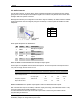
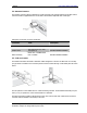
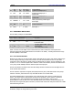
3.6 RS232 Serial Port
he modem supports a standard RS232 serial interface (EIA/TIA 574) via its 9 pin Sub-D connector,
own below. In line with serial communication terminology the GTR64 serial modem should be
nsidered as the
data circuit-terminating equipment
(DCE) and the external application or computer as
e
data terminating equipment
(DTE).
he electrical charact low:
T
sh
co
th
T eristics of the serial port signals are shown be
Pin Signal Dir Voltage
levels
Description
1 DCD O
> +4V
< –4V
Data carrier detect
2 RD O
> +4V
< –4V
Received data
3 TD I
> 2V
< 0.8V
Transmitted data
4 DTR I
> 2V
< 0.8V
Data terminal ready
5 GND - 0V Ground connection
6 DSR O
> +4V
< –4V
Data set ready
7 RTS I
>
< 0.8V
Request to send
2V
8 CTS O
> +4V
< –4V
Clear to send
9 RI O
> +4V
< –4V
Ring indicator
GTR64 Integrators Manual V.1.2 Pag. 17
Preliminary. Subject to change without prior notice