
Specifications


7.4. SOFTWARE DESIGN
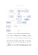
The processor executes the following FSMs, where each FSM is stepped
once per main loop cycle
4
:
1. Status display update
2. Poll peripherals
3. Battery charging & system health monitoring(see Section 8.4.2)
4. I
2
C communication
5. Timer
6. Report generation
7. GSM, SMS & Email communication
8. Command & settings processing
Prioritised interrupts are also used. Microchip’s 18F series has support
for two priority levels, with the higher priority ISR able to interrupt the lower
priority ISR. The low priority ISR services incoming RS232 data (storing it
in an array until a carriage return character is received and then releasing the
data for processing by the relevant FSM) and also the single push-button.
The high priority ISR is used f or the real time clock (RTC), with an interrupt
occurring every second.
7.4.1 Initialisation and Restoration of Configuration
Upon turn-on, the microprocessor initialises all internal peripherals as required,
including port direction registers, interrupts, the USART and I
2
C bus for
communication. Thereafter, the LCD is started and a welcome message
displayed. All state variables are reset to idle conditions and the real time
clock is started.
The PIC 18F series has the ability to self-write to Flash memory as
well as on-board EEPROM. The EEPROM memory is used to store device
4
Except for the I
2
C FSM which executes to completion – it is blocking once initiated.
Details in Section 7.4.5.
76