
Specifications


7.4. SOFTWARE DESIGN
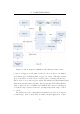
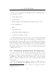
the master (the uplink module ) to a slave (any attached peripheral), followed
by nine data bytes from the slave to the master. It is assumed that the MSB
will be a status indication and the remaining eight bytes are data. For the
purposes of the RFID peripheral, the status byte represents the direction and
speed of the bird and the remaining eight bytes will b e used for the 64 bit
ID. This exchange makes use of I
2
C’s repeated start facility and Figure 7.4
illustrates a typical e xchange with a peripheral.
Figure 7.4: I
2
C protocol used in uplink module
Diagram based on illustration from [19].
The byte sent to the slave before retrieving the data is used to send
commands to the device (for example, power down, power up or sleep) and
is also useful if the peripheral device supplies more than one data type (for
example, the same weather monitoring peripheral can supply temperature,
wind speed and direction or atmospheric pressure). This initial master-slave
byte allows for the master to select one of the peripheral’s different responses.
7.4 Software De sign
The firmware runs on a microprocessor with limited processing power and
memory resources. It is thus important that the programming model be
fast, able to handle multiple processes and have a compact memory footprint.
Bearing this in mind, it was decided to use communicating finite state machines
(FSMs). Communication takes place via shared memory.
The development environment is provided by the manufacturer of the
chosen processor, Microchip’s MPLAB v7.4 with the C18 C-compiler. Included
with this package are interfaces to the processor’s on-board peripherals (such
as timers, communication busses, ADCs) and methods for controlling popular
attached hardware devices (such as I
2
C EEPROM devices and intelligent
LCD displays).
75