
Specifications


7.3. HARDWARE DESIGN
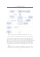
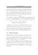
Figure 7.2: I
2
C master to slave multi-byte data exchange
Diagram based on illustration from [19]
An exchange from slave to master is similar, as illustrated in Figure 7.3.
The I
2
C specification does not permit a slave to initiate a transfer
3
, and
thus the master must request data from the slave device. The only difference
between this scenario and the previous one, is that the master now asserts
the SDA line during the LSb of the address byte, thereby requesting data
from (rather than writing data to) the slave. The master will release the
SCL line at this stage, but the slave will hold it low while it prepares
data for transmission. When released, the master clocks all 8 bits and
then acknowledges receipt by pulling the SDL line low for a ninth bit cycle.
Following this byte e xchange, another byte is transmitted and this continues
until the master has received all it requires. At this point, the master does
not send an acknowledge bit, but rather a NACK followed by a stop bit. The
slave’s I
2
C interface is then reset and it awaits another start bit followed by
its address.
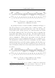
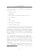
Figure 7.3: I
2
C slave to master multi-byte data exchange
Diagram based on illustration from [19]
The proto col used in this project consists of a single byte request from
3
unless it is a multi-master bus and the slave switches to master mode. But this
configuration is outside the scope of this document as it is not used in this project
74