
Specifications


7.3. HARDWARE DESIGN
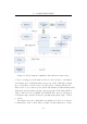
7.3.5 Peripheral Communication Bus
The choice to use I
2
C as an interface bus to the uplink module greatly
simplifies the hardware design. This bus is wired in a simple “AND” configuration
with each peripheral implementing an open collector interface on each of the
two lines – one for data (SDA) and another for clock (SCL). Each of the
lines are held high by a pull-up resistor. Any device may thus pull either line
low at any time. The I
2
C protocol requires one or more master devices and
allows for up to 1023 slave devices. There are various modes of operation,
including 7 bit or 10 bit addressing and high or low speed modes. For the
purposes of this project, high speed is also not a concern and the bus operates
at 100kHz, or low speed mode. It is unlikely that more than 128 devices will
ever be attached to the uplink module and so seven bit addressing is used.
Although eight bits are sent in the address field, the LSb of this byte is used
to indicate whether the following transfer is a read or a write operation,
resulting in an effective seven bit address.
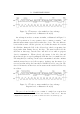
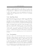
Slaves may not initiate a data transfer; the master must address the slave
first. Transmissions always begin with a “start” bit and terminate with a
“stop” bit. These are special bus events defined in the I
2
C specification and
can be seen in Figure 7.2. A start bit consists of the SDA line changing state
from high to low and then the SCL line following suit. A stop bit consists of
the SDA line changing from low to high after the SCL line. Under no other
circumstance may the SDA line change state while the SCL line is still high.
A stop bit resets all attached slaves’ I
2
C interfaces. It is common practice
to have repeated start conditions during a single exchange (used to change
between read and write mode). Only the master may clock the system, but
any slave may hold this line low to prevent clocking if it is not yet ready to
transmit or rece ive.
A typical data exchange of multiple bytes from master to slave is illustrated
in Figure 7.2. After each byte transmitted, the master releases the data bus,
and the slave device pulls it low to acknowledge the exchange. If the line
remains high, it is interpreted by the master as a unacknowledged. This
could, for example, be due to the slave device’s receive buffer overflowing. At
this point, the master will terminate the exchange by issuing a stop condition.
73