
Specifications

6.3. EVALUATION
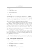
indefinitely for this animal at the second gate, a time-out is implemented.
If the animal does not trigger both gates within approximately 1 minute,
the record is flushed and an error counter incremented for status reporting
purposes. It is thus possible to determine how many penguins have not been
successfully tracked.
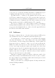
6.2.4 The upload FSM
Once this table has bee n established, it is a simple process to look through
all the entries and prepare the ones which have their status bytes set to “tag
moved in direction X-Y” for upload when the co-ordinator is polled. An
“upload state” variable stores the current state of the upload. It is either
idle, data waiting for upload, or, data sent. After the upload was successful,
the record is cleared, ready for a new entry. Details of the bus protocol can
be found in Section 7.3.5.
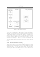
6.3 Evaluation
The device operates successfully; readers are polled sequentially, the times
between gate reads correctly determined and the resulting data is delive red
to an I
2
C master device upon request.
The co-ordinator operates the readers at near full speed: as soon as one
reader has completed a read cycle, the next one is triggered. The readers
require additional processing time to decode the data received from the tags
should these be present. Thus, fewer reads per second are performed when
there is a tag in one or both of the readers’ fields. This results in a lower
transmission duty cycle and thus reduced average power consumption figures.
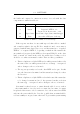
Average quiescent current for the entire RFID subsystem was measured
at 150mA for two single channel push-pull receivers and the co-ordinator.
Most of this power can be attributed to the status LEDs (which were of the
standard 20mA variety for this prototype). Recall that the readers required
5.5W for transmission. This results in a total average power consumption
for the entire RFID subsystem of 2.95W when no tags are present and
approximately 2.1W when there are tags within read range.
62