
Specifications

6.2. SOFTWARE
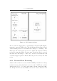
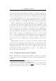
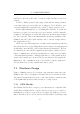
Figure 6.1: Global timer flowchart
In one of the two trigger states, a general purpose IO pin is pulled high to
trigger the connected RFID reader. The system timer is then started (based
around Timer0) and the reader FSM’s state changed to “Awaiting”. It is
then up to the received data processor to capture the response from the
reader and change the FSM to the next state. Should no data be received,
the timer state will change to “timed out”, and the reader FSM state will
cancel the trigger request for this module, flag an error and try the next
reader.
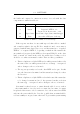
6.2.3 Received Data Processing
waits for a line of data to be received via the USART (ie it waits for a carriage
return character). After this has been received, the USART state variable
changes from “idle” to “decoding” with captured data in a temporary buffer.
If a transponder ID was successfully received, the data is extracted from
60