
Specifications

6.2. SOFTWARE
2. RFID reader
3. Received data processor
4. Upload data preparation
6.2.1 Timers
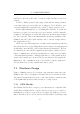
The Timer FSM can be in one of three states: either “stopped”, “running” or
“timed out”. The on-board peripheral Timer0 features an eight bit prescaler
(maximum of 256) and operates from the bus clock (in this case the 8MHz
crystal ÷ 4 giving a 2MHz clock). Thus, a maximum period of a little over
eight seconds is achievable w hen using the timer in 16 bit mode.
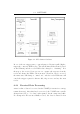
In order to obtain longer timing periods, Timer0 is used as a global system
timer which runs continuously with fixed interrupts every 250ms. A separate
software variable is created which contains a timer counter. This counter is
decremented every time Timer0 creates an interrupt (ie every 250ms). When
this software counter reaches zero, the timer state changes to “timed out”.
Thus, any delay greater than 250ms can be created, in multiples of 250ms.
Figure 6.1 illustrates the operation of this system.
A general function was written to initialise the timer counter variable
to the desired timer period: the user passes the required time interval (in
milliseconds) as an argument to the function and simply polls the timer state
to see when the period has expired.
The Timer0 interrupts are also used to increment the “elapsed time”
member of each record (details of this operation in the following sections).
6.2.2 RFID Reader Request FSM
The RFID reader FSM cycles through four states:
1. Trigger RFID reader0
2. Await RFID reader0 response or a time-out
3. Trigger RFID reader1
4. Await RFID reader1 response or a time-out
59