
Specifications
Chapter 6
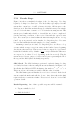
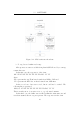
RFID Co-ordinator
The co-ordinator device acts as an intermediary between the RFID readers
and the uplink module. It must thus be able to communicate on two different
buses. The following sections discuss the hardware and software design of
this component.
6.1 Hardware
The hardware consists of a single microprocessor with interconnects to the
adjacent devices (RFID readers and uplink module). Power is supplied
through the uplink module connection and both supply rails (12V and 5V)
must be supplied to the RFID readers.
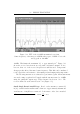
The RFID readers use a standard RS232 interface. Two readers will
be connected to a single co-ordinator and the co-ordinator thus requires
two RS232 interfaces. The PIC 18F452 only has one USART peripheral,
however. Two possible s olutions exist: construct a software USART using
two of the microprocessor’s general purpose peripheral pins, or, multiplex
the two devices into the single receiver. Since the readers will be triggered
sequentially, rather than in parallel, the two readers will not submit a response
to the co-ordinator simultaneously. Thus, a simple “OR” multiplexed bus
on the single receiver suffices. The co-ordinator’s RX line is normally held
high by a pull-up resistor, and either reader may pull it low through a signal
diode. When idling, this arrangement consumes no power. Communication
57