
Specifications

5.6. DESIGN EVALUATION
No tag found.
This response is also possible if the antenna becomes open loop or an internal
circuit fault exists.
5.6 Design Evaluation
5.6.1 Transmitter
Recall that 134.2kHz is not directly obtainable from the 8MHz crystal employed.
Thus, a form of direct digital synthesis (DDS) is used. By generating a
133.33kHz signal for two cycles followed by a 135.59kHz signal on every third
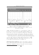
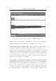
cycle, an average frequency of 134.09kHz is achieved. Figure 5.12 shows an
FFT plot of the positive half of the spectrum of the transmitted signal. The
spectral purity of this signal coupled with the resonant antenna ensures that
the system only responds to the fundamental frequency of the square wave.
Figure 5.12 shows a screen capture on an Agilent oscilloscope performing an
FFT plot of the antenna waveform signal us ing a Hanning window. This was
generated using the DDS technique outlined above, using the push-pull type
transmitter disc ussed in Section 5.4.2.
The power output devices in the single-ended design did not require
heatsinks at all — the cases of the IRFP250 s are sufficient to dis sipate all
produced heat at room temperatures (even when operated continuously).
The devices used in the push-pull design, however, do require heatsinks if
operated at high duty cycles. Small aluminium plates will serve as heatsinks
with temperature coefficients of approximately 10 degrees C per watt.
5.6.2 Antenna and Tag Orientation
Various antenna designs were considered with mixed results. Antenna tuning
proved to be critical. If the antenna was tuned to 134.2kHz then it resulted
in a very strong transmitted pulse. The tags, however, emit both 123.2kHz
and 134.2kHz signals. The consequence of such a set up is that the 123.2kHz
signal is not received at a similar amplitude and the receiver is unable to
decode the data stream. The antennae were thus tuned to approximately
50