
Specifications


5.5. SOFTWARE
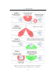
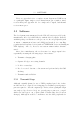
Peripheral Function
CCP1 Generate interrupt on every fourth e dge
Timer0 Implement timeout (20ms)
Timer3
Elapsed time between CCP interrupts
(coupled to CCP module)
Table 5.5: Microprocessor peripheral allocations during capture
an interrupt on every fourth rising edge. When this occurs, the CCP ISR
stores the value in Timer3’s counter in an array for later processing. Timer3
is then reset in order to time the period to the next fourth edge. The following
section of pseudo code illustrates this operation:
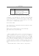
Preset Timer0 (20ms)
while (Timer0 has not overflowed) and (receive buffer not full)
Wait for CCP interrupt
{
Capture value in Timer3 register on every fourth edge
Reset Timer3 after every fourth edge
}
Timer3 is initialised with a prescaler of 4 from the bus frequency of
8MHz
6
. Recall that the two expected received frequencies are 123.4kHz and
134.2kHz. The frequencies of the interrupts are thus expected to be 30.85kHz
and 33.55kHz respectively (after the hardware divide by four). The values in
the stored array for each channel are thus expected to increment in values of
57 (2M Hz÷30.85k Hz) or 65 (2MHz÷33.55kHz) depending on the received
frequency. In this way the bit stream can be de termined during the decode
stage.
When the buffer is filled, or Timer0 overflows, decoding is started.
46