
Specifications


5.5. SOFTWARE
generation of these signals (since they can be muxed together to produce out-
of-phase waveforms), they were reserved for receive channels. Furthermore,
it is trivial to implement the transmit waveform generation in software.
In order to achieve the required charging p eriod (50ms or even 100ms),
one of the microprocessor’s timer peripherals were used. Timer0 was chosen
as it is independent from any other device operation (such as the capture
peripheral which uses Timer3 - see Section 5.5.2). Timer0 is started with
a time-out set to the desired period and a loop started which generates a
134.2kHz square wave.
Timing for the 134.2kHz generation was achieved by using “no operation”
(NOP) commands to generate the required delays. The pins were then
manually pulled high or low as required. As mentioned in Section
5.4.5,
a perfect 134.2kHz signal is not possible from the 8MHz crystal. Each loop
consists of three cycles: two with a period of 60 cycles (giving a 133.3kHz
clock) and one with a period of 59 cycles (giving a 135.6kHz clock). This
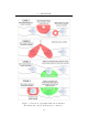
gives an average frequency of 134.08kHz. The spectral efficiency of this
configuration is sufficiently close to 134.2kHz to charge the tag (see Figure
5.12).
This loop of three cycles continues to execute until Timer0 times-out.
Thereafter, there is a 1ms guard period to allow the analogue circuitry to
recover and s tabilise before the capturing begins.
5.5.2 Capture Stage
The PIC18F452 features two Capture, Compare, PWM (CCP) peripherals
which are capable of identifying edges and generating interrupts when these
occur. Furthermore, they include a hardware divide by four function which
allows for the elapsed time between four edges to be measured without
introducing additional processor overheads. The CCP modules operate in
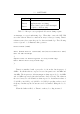
conjunction with Timer3. Table 5.5 shows the allocation of the various
microprocessor peripherals used during the capture stage.
Timer0 is again used to implement a time-out of the receive period. It is
limited to 20ms (recall that a receive cycle is guaranteed to complete within
this time – see Section 5.3 for details). A CCP unit is configured to generate
45