
Specifications


5.5. SOFTWARE
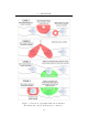
Please see appendix A.1 for a complete circuit diagram and PCB layout
of a push-pull output, single receiver channel interrogator (with no tuned
receiver filter) and appendix A.1 for a single-ended output, dual-channel
receiver interrogator.
5.5 Software
The development environment used for the PIC 18F series is provided by the
manufacturer, Microchip’s MPL AB v7.4 with the C18 C-compiler. Included
with this package are interfaces to the processor’s onboard peripherals (such
as timers, communication buses and ADCs) and methods for controlling
popular attached hardware devices (such as I
2
C EEPROM devices and intelligent
LCD displays). All code, however, was custom written unless otherwise
stated.
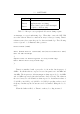
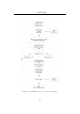
After device initialisation, the reader waits for a trigger input before
sequentially executing the following s tages of its software:
1. Transmit a charging pulse.
2. Capture all edges on receiving channels.
3. Look for a start byte.
4. Decode received data into a bit stream and perform bit-by-bit CRC
checking.
5. Transmit result via RS232.
5.5.1 Transmit Stage
Although originally planned to use a PWM peripheral pin, both of these
modules were now occupied for receiving purposes and thus a general purpose
pin was required to drive the output stage. In fact, when a push-pull design
was employed (see Section 5.4.2), two general purpose pins were occupied
which were 180 degrees out of phase (with dead-time introduced between
changes). Although it would be convenient to use the CCP peripherals for
44