
Specifications


5.4. HARDWARE
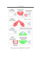
square-wave edges. An on-board RS232 interface will be used to transmit
the decoded data to the RFID co-ordinator.
Included in all designs is an In-Circuit Debugging (I CD) interface for
in-field debugging and reprogramming.
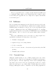
Property 68HC908JK3 PIC 18F452 PIC 18F4620
FLASH (Kbytes) 4 32 64
RAM (bytes) 128 1536 3986
Max speed (MIPS) 8 10 10
Timer peripherals 1 4 4
Timer channels 2 2 2
Additional fe atures Low cost HW multiply HW multiply
Low pin count USART USART
4 x PLL 4 x PLL
Divide-by-four- Divide-by-four-
capture prescaler capture prescaler
HW comparator
Table 5.4: Summary of considered microprocessors’ features
relevant to the RFID reader
Initial design based on 68HC908JK3
Freescale’s 68HC908JK3 was initially chosen as the development platform
as it appeared to have all the required components. However, the device was
too slow to decode the incoming bit stream on-the- fly and had insufficient
RAM for capturing all the raw data for off-line processing. In an attempt
to remedy the situation, a hardware divide-by-four (binary counter) was
inserted before the JK3. Recall that each transmitted bit is 16 cycles long.
After the hardware divider, each bit would now effectively consist of four
edges. This sampling rate is sufficient to allow for digital filtering of the
received signal. Unfortunately, even with the device running at full speed
(8MHz), it was not possible to decode the data as it was received. And
the processor’s 128bytes of RAM is still not able to accommodate all 512
41