
Specifications


5.4. HARDWARE
result in a high received voltage at the transponder. As outlined in Section
5.6, the number of turns on the antenna had very little influence on the
receiver’s performance: if a receiving antenna with a few turns is used, the
receiver chain’s gain is simply increased to compensate and produce similar
results.
What is of consequence is the transmitter’s inductance: it should remain
low enough to pass a significant current at 132.4kHz during the charging
phase from a 12V supply. As more turns are added to the transmitting
antenna, the inductance of the loop increases and since the supply voltage
and operation frequency remains constant, the current through the inductor
decreases. The undesirable consequence of such an action is a decrease
in transmitter power. The Texas Instruments Series 2000 antennae have
inductances of approximately 27µH [
15].
Many antennae were constructed and evaluated. Ultimately, it was decided
to use a single antenna for receiving and transmitting with a designed inductance
of 50µH. The number of turns on the antenna would ultimately depend on
the physical size, shape and diameter of the wire used. The proposed final
design uses a rectangular antenna me asuring 260mm × 230mm.
5.4.5 Processor
Prior to this project, the only experience we had with microprocessors was
with Freescale’s HC08 series. After finding an 68HC908JK3 inadequate for
the task, Microchip’s PIC 18F452 and later a PIC 18F4620 were considered.
The details of the design as well as the benefits and shortcomings of each
device are outlined in the sections which follow.
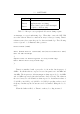
The microprocessor must be capable of:
• Generating a logic-level square wave at 134.2kHz
• Determining the frequency of a received square-wave
• Reporting the data to the RFID co-ordinator
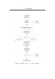
The initial solution is to use two timer modules, one to generate the
transmitting pulse and the second to determine the elapsed time between
40