
Specifications


5.4. HARDWARE
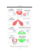
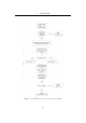
Since the Series 2000 tags do not allow for the reading of multiple tags
simultaneously, both reads will fail and no penguin will be detected.
Case three illustrates a gate antenna in a vertical orientation. The read
is successful provided that the tags are at a similar height to one of the
horizontal members of the antenna (ie the top or bottom edge). A dead zone
exists in the centre of the antenna.
The final case illustrates a gate antenna placed horizontally. If placed
alongside the path, the read is successful provided that the receiving antenna
is at a similar height to the transp onder. If placed on the ground beneath
the penguins, the required read range would need to be approximately half
a metre. In order to achieve this range using a gate antenna, a high power
transmitter and highly sensitive receiver would be required. Such a system
would be costly to construct and have a high power consumption and is thus
not suitable for a low-cost battery powered device (should the mains fail).
After considering these options, it was de cided to use an inductive loop
(gate) antenna rather than a ferrite stick antenna with the intention of placing
it alongside the penguin path, either in a horizontal or a vertical position.
The ideal orientation w ill be determined experimentally.
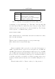
The commercial unit used in the existing system cost in excess of ZAR1200
(depending on the size). Since the aim of this project is to produce a low
cost de vice, the use of a commercial antenna is not possible. Sizing of
the replacement custom unit will be similar to the existing antenna (Texas
Instruments’s “small” Series 2000 gate antenna). Please see Figure 5.1 for
a diagram of the various Series 2000 antennae.
Antenna Operation and Design
The antennae of the transmitter and receiver of low frequency RFID systems
form inductive couplings. Our initial consideration was that the the windings
on the antennae of the reader and the transponder can be thought of as
forming a transformer. Given that the number of turns on the transponder’s
antenna is fixed (since these are purchased, commercial units), we considered
using a large number of turns on the receiving antenna to result in a high
received voltage and a small number of turns on the charging antenna to
39