
Specifications


5.4. HARDWARE
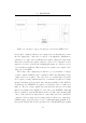
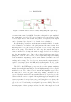
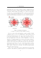
stick antennae placed in a vertical orientation. Figure 5.9 illustrates the read
fields generated by the two antenna designs in both horizontal and vertical
orientations, with the transponders assumed to be vertical. It represents a
top-down view of a typical penguin path. The coloured zones represe nt the
read fields assuming that the transponders are of the 32mm glass variety (ie
with ferrite stick antennae) and pass the receiver in a vertical orientation.
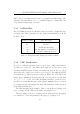
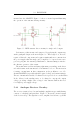
Figure 5.8: Antenna field patterns
for ferrite rod (“stick”) and gate antennae, from [15]
In case one, the reader’s stick antenna is oriented vertically. In this
configuration, there is a dead zone at azimuth angles of approximately 45degrees
from the horizontal (referenced to the centre of the reader stick as indicated
by the field patterns in Figure 5.8). Thus, if the transponder is not at
the same height as the receiver, the read fails. Furthermore, even if both
antennae are at similar heights, the read range is short in this orientation.
Ultimately, stick antennae are designed to be oriented end-to-end. If a stick
antenna could be buried in the ground under the path, it is possible that the
system would work. However, in order to achieve the necessary read range
(approximately half a metre), a narrow, focused, highly directional beam
will be required. This narrow beam width could result in penguins passing
undetected between scan cycles.
In the second case, the dual read zones of the stick reader in a horizontal
orientation could result in two penguins being in the read zones simultaneously.
37