
Specifications


5.4. HARDWARE
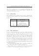
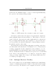
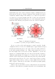
Figure 5.4: Overview of proposed microprocessor-based RFID reader
heat would be dissipated in the power output devices as they linearly convert
the 12V supply into a sine wave (a class A or B amplifier). Furthermore,
generation of a pure tone is difficult and requires additional components.
Since the reader already requires a microprocess or for decoding the received
signal, we decided to generate the charging pulse using one of the processor’s
on-board timer peripherals. This would provide a square wave output of 50%
duty cycle at 134.2kHz.
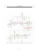
The design of the output stage is critical to good performance. Voltages
on these output terminals can be as high as 200V and thus high voltage
output de vices are required. The only device at our university electronics
store capable of such potentials with a low on resistance (required for a high-
Q tuned antenna) and reasonable drive current capability is IR’s IRFP250
N-channel power MOSFET. It requires over 10V gate drive to ensure it is
fully on. The low voltage digital waveform from the microprocessor must
thus be level shifted and amplified to drive the power MOSFET. Although
ICs are available to perform this function, they are still costly and this result
can be easily achieved by using discrete components as follows: An LM311
comparator level-crossing detector (with positive feedback for a “snap-snap”
Schmitt trigger response) drives a pair of push-pull signal transistors (to
increase the current drive for the capacitive load of the MOSFET gate) which
32