
Specifications


5.4. HARDWARE
accommodate the RFID readers (all other system components require 5V or
less). The potential differences across the antenna terminals are expected to
reach into the hundreds of volts due to the high Q tuned antenna design.
This a safety concern and requires careful circuit planning and component
selection.
When considering the detector for the RFID reader, it is important to
remember that the bit length of the received signal is only 16 cycles long. This
all but eliminates the possibility for tone decoders (which lock onto received
frequencies and are capable of detecting signals in high noise conditions) as
the lock-on times are usually longer
3
. Filtering of the received signal also
presents a challenge: the filters must respond within the 16 cycles to prevent
signal smearing.
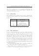
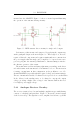
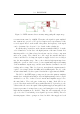
As mentioned in Section 4.2, the RFID peripheral will consist of a co-
ordinator and two readers. Each RFID reader can be sub-divided into
operational components as follows:
• Microprocessor
• Antenna driving circuitry
• Analogue receiver circuitry
• Antenna
The configuration is illustrated in Figure 5.4.
Two of these reader devices will be connected to a co-ordinator which
calculates the direction of tag movements (from reader 1 to 2 or vice-versa).
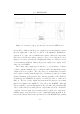
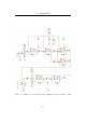
5.4.2 Antenna Driving Circuitry
The purpose of the antenna driving circuitry is to provide the antenna with
a high driving c urrent to charge the transponder.
Ideally, the antenna should be driven by a pure sine wave at exactly
134.2kHz. However, driving the antenna with a sine wave would mean that
3
For example, a pair of National’s LM567 s will require over 50 cycles to differentiate
reliably between 123kHz and 134kHz[14]
31