
Specifications


5.3. TRANSPONDER DATA FORMAT AND PROTOCOL
If the transponder’s capacitor has be en sufficiently charged, it immediately
begins transmitting after detecting the termination of the charge signal.
This signal is in the form of non-encoded (raw) binary frequency shift keyed
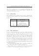
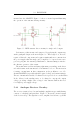
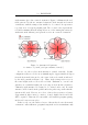
(BFSK) sequence of 128bits. Figure 5.3 illustrates the data frame format.
Figure 5.3: 64bit Read-Only transponder data format, from [1]
The start byte is used to identify the type of transponder. For example,
RO tags have a start byte of 0x7E whereas RW tags have a start byte of
0xFE[1].
The tag stores 64 bits of identification data and a further 16 bits for CRC
integrity checking. Each bit consists of 16 cycles at the given frequency:
• Logic low is given by a 134.2kHz signal;
• Logic high is given by a 123.2kHz signal.
Because each bit is represented by a constant 16 cycles at different frequencies,
the bit periods differ. A low bit period typically takes 119µs and a high bit
130µs. Irrespective of the bit sequence transmitted, the entire message is
guaranteed to have completed within 20ms.
The system does not support reading multiple tags in a single reader
field as the transponders begin transmitting their data immediately after
the termination of the charge pulse. If multiple tags were to be present
in the same reader field, all transponders would thus begin transmitting
simultaneously. Although the reader would receive multiple signals, it would
be impossible to differentiate between the signals and the CRC check fails.
A successful read is impossible until the surplus tags are removed from the
reader’s field. The implication is that if two penguins are allowed to enter
the read field simultaneously, neither will be identified, although the system
28