
Specifications


5.1. INTRODUCTION
have short read ranges of only a few centimetres [5]. Fixed installations often
have higher power outputs and larger antennae with increased field sizes
for improved reliability and range. More exotic solutions include multiple
antennae for reading specific areas or dedicated, independent transmit/receive
antennae.
Antennae
Different antennae provide different read-field shapes. These can be tailored
to suit the application. For example, a strongly directional antenna can be
constructed which provides a long read range in one direction only. This is
useful if there are multiple tags in the vicinity and the operator would like to
single out one tag by pointing the reader at it. A common means of achieving
such a field in low frequency systems is by creating a winding on ferrite rods.
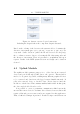
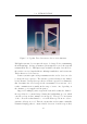
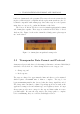
The other popular antenna structure is simply a coil of wire (known as a
gate antenna). The fields produced by both antenna types are illustrated
in Figure 5.8, reproduced from Texas Instruments’s technical handbook on
their Series 2000 antennae. The physical units in varying sizes are shown in
Figure 5.1. Note that the existing system on the island used the small gate
antenna depic ted in the lower left of Figure 5.1.
5.1.2 Active versus Passive Systems
RFID systems are often categorised according to the tag’s power supply -
active or pass ive.
Passive RFID
Passive tags do not have on-board power supplies and need to be powered
by the EM wave from the reader. Two systems are in operation: full-duplex
and half-duplex. In half-duplex systems, the tags need to be charged before
they can transmit their data. The reader emits an EM wave at the tag’s
operation frequency and the tag stores the received RF energy in a small,
integrated capacitor. Once fully charged, the reader stops emitting the
charging waveform and this stored energy is used to transmit the tag’s data.
22