
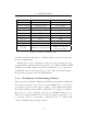
Specifications


4.3. UPLINK MODULE
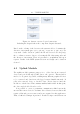
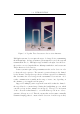
Figure 4.2: System overview: Logical connections
Including the chapters where the component design is discussed.
Based on the ordering of the detection, the system is able to determine the
direction of movement (gate one to gate two, or gate two to gate one). For
every such “double detection” (where the ID was detected at both gates),
the co-ordinator creates a data record, storing the ID of the transponder and
the direction of movement. These are presented to an uplink module upon
request. Details of the RFID system selection and design can be found in
Section 5.
4.3 Uplink Module
The uplink module’s primary purpose is to collect data from connected
devices and periodically upload this data to the operator. This module is
made to be as generic as possible, enabling many different peripheral devices
to be connected and data from each logged at user-definable intervals. It
polls each connected device to check for data. If new data is found, the
module records the data. This continues until its buffer is full. At this point,
the device uploads all collected records.
It is possible to create a permanent communication link between the
user and the remote device for real-time data collection, however, this would
require additional power resources and is not required for this application.
Thus, a buffered technique is preferred. Detailed design considerations can
18