
Specifications

8.5. MEASUREMENTS
8.5 Measurements
8.5.1 Power Supply Efficiency
The total efficiency of the converters is measured to be approximately 85%
when the GSM module is powered. There is a further loss in the form of
the 0.6V drop across the Darlington which switches the 12V battery supply
to the 3.8V switching regulator. Recall that this is necessary to provide a
soft-switching ability to the 3.8V line (which is only required when the GSM
unit is to be powered).
When the GSM unit is not powered, and no LEDs are illuminated (i.e.
under light-load conditions — only the processor running, drawing approximately
12mA) efficiency drops to 60%. This is mainly attributed to the now-
significant switching regulator’s quiescent current of 4mA.
8.5.2 Calculated Backup Time
Under normal operating conditions, the uplink module requires 85mW from
the 5V rail and the RFID subsystem 750mW on the 5V rail and 2.2W on
the 12V rail. The only losses on the 12V rail are due to the resistive losses in
the connecting cables. If we consider these to be negligible and the efficiency
of the SMPS to be approximately 80%, the total average power drawn from
the battery will be 3.5W.
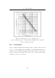
This equates to an average discharge current of 292mA. Figure 8.7 illustrates
the discharge period versus the discharge current for a Panasonic SLA 7.2Ah
12V battery [24]. At higher discharge currents, the battery capacity is
decreased. In the field, the system device will regularly require peak currents
in excess of 500mA (due to the RFID readers), which will sporadically
increase to over 1.2A when the GSM unit is in use. The backup time is
thus unlikely to be as high as the 30 hours which the average dis charge rate
of 292mA implies. However, considering how short these pulses are likely to
be, and the infrequency with which they will occur, it is safe to extrapolate
that the backup time afforded by a s ingle 7.2Ah battery is likely to be in
excess of 24 hours.
100