
Specifications

8.4. BATTERY SELECTION AND CHARGING
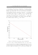
considered is paralleling two or more such batteries to further boost backup
time. Refer to Section 8.5 for power consumption figures and estimated
battery life time.
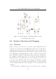
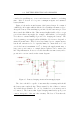
Figure 8.5 shows the circuit diagram of the battery charger. It consists of
a full-bridge AC rectifier which is switched by a Darlington transistor, Q4, to
charge the battery. This switching is performed by the same microprocessor
that controls the GSM module. This circuit is highly flexible, able to accept
power from almost any supply (for example, wind turbine or solar panel).
Note that no current limiting is provided for charging the battery. The
device’s primary power supply will in all likelihood be from a solar panel or
mains AC transformer. These devices have limited power outputs anyway,
but should current need to be expressly limited to ensure that we do not
exceed the battery’s maximum of 3A
2
or damage the supply transformer, a
large series power resistor or a simple linear regulator can be inserted in-
line. Experimentation, however, revealed that this was unnecessary and so
provision for one is not made in the circuit diagram.
Figure 8.5: Battery charging circuit and main supply input.
The device should be capable of automatically re-starting itself should
the battery run completely flat. This is ensured by the addition of resistor
R45 which biases transistor T9 “on” by default as soon as main power is
re-connected. The battery thus begins charging immediately upon power
connect, irrespective of the any other circuitry. The base of T9 is then also
2
40% of 7.5Ah.
97