
Specifications

8.3. REGULATOR SELECTION
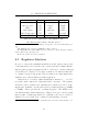
Device Voltage Ave Current Ave Power
RFID Co-ordinator 5.0V 50mA
a
250mW
Microprocessors & misc Logic 5.0V 2×50mA
b
500mW
Output antenna drivers 12.8V
c
2 × 20% × 420mA
d
2.2W
TOTAL POWER 3W
Table 8.2: Power requirements of the RFID subsystem.
All values measured on prototype push-pull device .
a
Single PIC18F452 operating at 8MHz with HS oscillator enabled with two high-
efficiency LEDs.
b
Two independent PIC 18F452s operating at 32MHz (8MHz with 4x PLL enabled)
running continuously with four low-duty cycle high efficiency LEDs.
c
Power supply voltage will vary with battery level. 12.8V represents a worst-case
condition when the battery is fully-charged and the voltage is at a maximum.
d
Two reader modules operating at two reads per second each, with 100ms charge pulses.
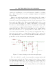
8.3.1 Linear Technology’s LT1765
Initially, Linear Technology’s L1765 was chosen due to its high switching
frequency of 1.25MHz which promised low interference in the RFID band
and small inductor requirements. Furthermore, it claimed switching currents
of 3A with efficiencies in excess of 90%. The devices are only available in
surface mount packages, which are awkward for prototyping purposes.
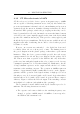
When benchmarking the modules using the manufacturer’s recommended
application circuit [20], it was found that they produced significant amounts
of heat and were not as efficient as claimed. Furthermore, the stability at the
operating frequency was questionable. Both problems could be attributed to
poor PCB layout and/or poor thermal coupling of the device to the PCB.
Experimentation revealed that we could only reliably extract approximately
1.5A. The datasheet claims to incorporate thermal shutdown and full cycle-
by-cycle current control, however, after destroying two devices while drawing
1.5A, it was decided that they would not meet the requirements of the GSM
module (which draws peaks of 2A).
91