Installation & Operation Manual RT9 Powershelf Document: 158-1806-01.doc Date: 21 December 2005 © Rectifier Technologies Pacific Pty Ltd ACN 058 107 707 Wave Communications Pty Ltd Unit 5, 97 Jijaws St Sumner Park QLD 4074 TEL: 07 3279 0600 FAX: 07 3279 0544 EMAIL: sales@wavecomeng.com.au WEBSITE: www.wavecomeng.com.
RT9 Powershelf Rectifier Technologies Table of Contents 1. General Warnings ...............................................................................4 2. Configuration ..............................................................................................................5 2.1 General Description ...............................................................................................5 2.2 3. 4. System Description ......................................................................
RT9 Powershelf 5. Operation ..................................................................................................................24 Summary of MiniCSU-3 front panel controls .................................................................24 5.1 Alpha-numeric Display..................................................................................25 5.1.2 Front Panel Pushbuttons ..............................................................................25 5.1.
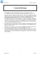
RT9 Powershelf Rectifier Technologies 1. General Warnings 1. This equipment has been designed to be used only in restricted access areas. 2. This equipment must only be serviced by authorised and qualified service personnel. 3. Operators should not attempt to repair faulty units. There are no operator serviceable parts inside. All fuses are only replaced as part of a repair procedure in a repair facility by authorised personnel and not as a maintenance procedure on site. 4.
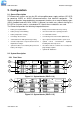
RT9 Powershelf Rectifier Technologies 2. Configuration 2.1 General Description RT9 Powershelf systems are turn-key DC uninterruptible power supply solutions (DC UPS) for powering 24VDC or 48VDC telecommunications and industrial equipment. The Powershelf provides integrated battery management functions for a range of battery types (VRLA, flooded Lead-acid, NiCd, Ni-MH, Li-polymer) to enable easy commissioning of a DC UPS or it can be used as a standalone DC source when no batteries are used.
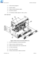
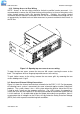
RT9 Powershelf Rectifier Technologies (1) Rack mounting magazine (2) Rectifier module (3) Battery (& load) distribution module (4) MiniCSU-3 controller (5) AC distribution module (option on some systems) 2.2.2 Rear View Figure 2.
RT9 Powershelf 1 Rectifier Technologies 2 3 4 5 6 7 8 Figure 2.
RT9 Powershelf Rectifier Technologies 3. Installation 3.1 Mounting the Powershelf The Powershelf is mounted into a standard 19” rack using M5 or M6 screws and cage nuts. For systems larger than 4U (rack units) in height, multiple standard Powershelf magazines are strapped together by four of 18x63mm strapping plates – two at the rear that must remain in place, and two on the front that can be removed once the shelf is secured in the rack.
RT9 Powershelf Rectifier Technologies 3.1.2 Gaining Access to Rear Wiring NOTE: Access to the rear wiring should be limited to qualified service personnel. It is recommended to remove the AC power before gaining access to the rear wiring due to the safety hazard present inside the electrical enclosure.
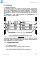
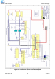
RT9 Powershelf Rectifier Technologies Figure 3.3 Powershelf internal schematic diagram 158-1806-01.
RT9 Powershelf Rectifier Technologies The switched battery cables (-ve in a –48V system) terminate on the copper bars of the battery distribution module (item 2 in Figure 2.3), while the battery return cables terminate on the common return bar (item 3 in Figure 2.3). The battery distribution module can be configured for up to four battery strings with the appropriate number of return cable termination points being available on the common bar.
RT9 Powershelf Rectifier Technologies 3.3.1 Factory Supplied Configurations Powershelves without internal AC distribution (eg. PSLF-1115), unless specially ordered, are configured with each rectifier active line being terminated in an individual DIN rail terminal block (beige) and the remaining AC line is connected to a common neutral bar (blue terminal blocks).
RT9 Powershelf Rectifier Technologies 3.3.3 3 phase star – individual protected external feeds Remove the link connecting the active terminals “A” together. Connect one phase wire per “A” terminal. Connect the neutral wires to the common neutral terminals. Figure 3.6 3.3.4 3 phase delta – individual protected external feeds Phase-to-phase (208VAC) connections require that the AC terminal blocks for the neutral be replaced with individual active line terminals.
RT9 Powershelf Rectifier Technologies 3.3.5 Surge protection requirements The rectifiers are internally protected for surges up to 6kV/3kA. For higher levels of protection, particularly for sites with high incidence of lightning or switching surges, additional surge protection is required on the AC feed to the Powershelf.
RT9 Powershelf Rectifier Technologies 3.4 Bulk Load connections Figure 3.9 A bulk load can either be a single large load, or a cable connection to an additional, external DC distribution unit. There are two M6 studs available for securing either 2 cables with single-hole lugs or a cable with double-hole lugs. Single hole lugged cables will require additional cable tying to prevent the cable from rotating on the studs.
RT9 Powershelf Rectifier Technologies Figure 3.10 3.6 Battery connections Figure 3.11 For –48VDC systems, the battery negative cables are terminated on the switched line terminals of the battery distribution module (shown above), while the battery positive cables are all tied to the common return bar. The cables can be either brought out through the cut out adjacent to the return bar, or through the break-out slot in the top cover.
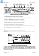
RT9 Powershelf Rectifier Technologies 3.7 Temperature Sensors The optional sensors for measuring ambient and battery temperature are the same device (Part No. 804-1100-01). The system auto-detects if the sensor is plugged into one of the positions (4) or (5) shown in Figure 2.4. If no sensor is installed, the MiniCSU-3 will show “Not Available” in the menu items for the temperature measurements. Locate the ambient sensor close to the intake air zone of the Powershelf.
RT9 Powershelf Rectifier Technologies 3.9 MiniCSU-3 Power Connections Power for the MiniCSU-3 and its peripherals is derived from the DC bus or the highest charged battery. The Battery distribution module has reverse polarity protection circuit that also serves to provide an “or-ing” of the highest supply voltage for the MiniCSU-3. There is one common connection to the +VE bus (in the case of a –48V system) and one connection each to the battery –VE bar on the LVDS and the –VE DC bus connection.
RT9 Powershelf Rectifier Technologies The following sections describe the interfaces in more detail and cover some of the set up requirements for the more advanced interfaces. 3.11.1 Isolated RS232 Interface This interface should be used if the distance between the Powershelf and a monitoring PC is not greater than 15 meters. The module has standard 9-pin D-type connector. For connection to a PC a “null modem” (or “cross-over”) cable should be used. Refer to the Operation section of this manual. 3.11.
RT9 Powershelf Rectifier Technologies For connection to a PC a suitable interface should be used (ie. Plastic Fibre Modem SY – 1025101 manufactured by Foxbro Company, a division of Invensys). Optical cable/connectors are not provided. It can be ordered from your local Hewlett Packard distributor (ask for Versatile Link Fiber Optic accessories data sheet). 3.11.4 TCP/IP and WebCSU Interfaces The interface is a 10/100BASE-T Ethernet adaptor.
RT9 Powershelf Rectifier Technologies Note: If the country in which you intend to use the Integrated Modem is not listed, a generic code ‘99’ or ‘FD’ can be tried.
RT9 Powershelf Rectifier Technologies Note: the above connection information is relevant when the LVDS is a battery disconnect. If the LVDS is a load disconnect, the DC bus side wiring of the circuit breakers is reversed such that the battery connections come off the DC bus side of the LVDS, while the load is taken off the LVDS common busbar. Diode V27 in the battery distribution module must be replaced with a shorting link for the LVDS to work as a load disconnect. Figure 3.15 Figure 3.
RT9 Powershelf Rectifier Technologies 4. Commissioning With all the batteries, load and AC cabling wired, and checked for correct polarity, the system is commissioned by the following steps: • Ensure no rectifiers are installed in the Powershelf and no load is applied. • Close Battery breaker 1 and check (audible) that the LVDS closes. • Plug in the MiniCSU-3 controller – it should power up off the battery. If not, it is possible that the battery polarity is reversed.
RT9 Powershelf Rectifier Technologies 5. Operation System operation is controlled by the MiniCSU-3 system controller. As a result, operation information for the system is directly related to the operation of the MiniCSU-3 as described in this section.
RT9 Powershelf Rectifier Technologies 5.1 MiniCSU-3 Components 5.1.1 Alpha-numeric Display The user interface is a two-line by 16 character alphanumeric OLED display. The 5mm high characters normally display output voltage and current as well as the system status Float (FL) or Equalise (EQ). This is the default or “home” screen.
RT9 Powershelf Rectifier Technologies 5.2 MiniCSU-3 Security & Alarms 5.2.1 Password security MiniCSU-3 features password security for setting of parameter. A valid password is an alphanumerical code having minimum three and maximum eight characters. Units leave the factory without a pre-programmed password and the security function is not active. To activate the security, a password must be programmed. Once that is done, security can be enabled. 5.2.1.
RT9 Powershelf Rectifier Technologies 5.2.3 MiniCSU-3 Alarms A list of all the possible alarms that can be enunciated is shown in the following table.
RT9 Powershelf Rectifier Technologies Alarm Name Comments LED Cell %dev Low One or more cells being monitored by BCM is too low % deviation from the mean battery cell voltage A Range SMR SMR parameter range error. MiniCSU-3 could not overwrite values A Site Monitor Alarm present from the site monitor module. See site monitor menu for details of alarm channel.
RT9 Powershelf Rectifier Technologies 5.3 Navigating MiniCSU-3 Functions 5.3.1 Base Menu (System Level Functions) Home screen - FL indicates float mode and FLC indicates float mode with battery temperature compensation 25.2A 54.3V FL Indicates that the front panel is locked.
RT9 Powershelf Rectifier Technologies (Base Menu continued) Sets MiniCSU-3 access code address ENTER Access Code 0000000 Modify Value up/down ENTER to accept ENTER Date Format DD/MM/YYYY Modify Value up/down ENTER to accept ENTER Date 25/12/2005 Time 01:11:11 ENTER selects hours, minutes, day, month or year INC/DEC modifies value ENTER Alarm Report Off INC/DEC toggles state ENTER to accept ENTER Daily Report Off (If Daily Rep not = Off) INC/DEC toggles state ENTER to accept ENTER Daily Rep Time
RT9 Powershelf Rectifier Technologies (Base Menu continued) ENTER 3-ph AC Monitor Off INC/DEC toggles state ENTER to accept (If 3-ph AC Monitor not = Off) ENTER 3ph AC Vhi Alarm 260V Modify Value up/down ENTER to accept ENTER 3ph AC Vlo Alarm 200V Modify Value up/down ENTER to accept ENTER 3ph AC fhi Alarm 55.0Hz Modify Value up/down ENTER to accept ENTER 3ph AC flo Alarm 45.0Hz Modify Value up/down ENTER to accept ENTER 3ph AC FS Curr.
RT9 Powershelf Rectifier Technologies 5.3.2 SMR Menu (Rectifier Specific Functions) Home Screen 25.2A 54.3V FL ⇒ SMR Button SMR software version ENTER SMR1 13.2A 58°C (↑) SMR1 S/W 137901 SMR Electronic Serial # DEC S/N 0102050500012 INC (↓) ENTER SMR2 : SMR2 : Additional screens if more SMRs are declared S/N : Float Voltage - SMR Default SMR Float 54.5V *Cannot be adjusted here SMR Equalise 56.
RT9 Powershelf Rectifier Technologies 5.3.4 Battery Menu (Battery Specific Functions) Home Screen 25.2A 54.
RT9 Powershelf Rectifier Technologies (Battery Menu continued) Enable/disable Equalisation charging ENTER Equalisation On ENTER toggles state Off / On Charge current limit for battery voltage between float & equalise ENTER BILim Vb>Vfl 20A Modify Value up/down ENTER to accept System Equalise voltage without BTC. Sense point voltage regulated to this value ENTER System Equalise 56.
RT9 Powershelf Rectifier Technologies 6. Troubleshooting Symptom Likely Causes Action Rectifiers do not power up – no LEDs lit on front panel AC power is not connected or internal fuse blown or rectifier not properly plugged in. Re-insert rectifier(s) and make sure the rear connections are good. Confirm that AC power is available to the rectifier backplanes. Replace the rectifier module if the unit is suspected to have failed.
RT9 Powershelf Symptom “SMR Urgent” alarm activated All units are latched off as HVSD A rectifier is indicating “SMR Off” or “No Response” on the MiniCSU-3 SMR display Rectifier Technologies Likely Causes Action One or many SMRs are off due to AC power failure, internal faults, incorrect command signal from MiniCSU-3 or all rectifiers are in current limit Check the AC power and restore. Absolute Overvoltage shutdown protection activated. The system is likely to have no load and without a battery.
RT9 Powershelf Rectifier Technologies 6.1 To Remove a Rectifier Module or a MiniCSU-3 Controller Lift the securing latch in the centre divider adjacent to the module and pull the module out of the Powershelf. When removing modules, especially if the ambient temperature is high and the unit has been operating at maximum load, avoid skin contact with the metal casing as it may be too hot to touch. Pull the unit halfway out of the magazine and let cool for 2-3 minutes before handling. 6.
RT9 Powershelf Rectifier Technologies 7. Appendix A – Setting Up Network Interfaces 7.1 Programming IP addresses using DeviceInstaller software. This is the simplest way of programming the interface operating parameters, no high level of computer skills is required. DeviceInstaller is a software utility package developed by Lantronix. It includes a number of handy tools making programming of various parameters and firmware update very easy.
RT9 Powershelf Rectifier Technologies • If the new address is listed, click “Save” button. Details of new device will be added to the DeviceInstaller data base. • If the new address is NOT listed, repeat the programming procedure. 7.1.3 Preparations for gateway address set up • From your network administrator obtain the gateway IP address • Connect a PC to the controller’s network interface (directly or via a network). • Power-up the controller. • Start DeviceInstaller program. 7.1.
RT9 Powershelf Rectifier Technologies Type 0 followed by Enter. The first item in server configuration is local IP address. That has been programmed already, but it is necessary to go through all bytes. Information in brackets shows current setting, which can be modified by typing new entry followed by Enter key. Next item after IP address reads: Set gateway IP address (N) [or (Y)] If value is (Y) – just press Enter, if (N) – press ‘Y’ followed by enter.
RT9 Powershelf Rectifier Technologies working. Once there is at least one additional entry in the ARP table, use the following command to ARP an IP address to the unit: arp -s 192.168.0.97 00-20-4a-xx-xx-xx 3. Open a Telnet connection to port 1. The connection will fail quickly, but the unit will temporarily change its IP address to the one designated in this step. telnet 192.168.0.97 1 4. Finally, open a Telnet connection to port 9999, and press Enter within three seconds to go into Setup Mode.
RT9 Powershelf Rectifier Technologies Serial Number 1297-041 Software Version V03.9 (000211) Press Enter to go into Setup Mode 4. To enter the Setup Mode, you must press Enter within 3 seconds. *** basic parameters Hardware: Ethernet Autodetect IP addr 192.168.000.
RT9 Powershelf Rectifier Technologies Gateway Address The gateway address, or router, allows communication to other LAN segments. The gateway address should be the IP address of the router connected to the same LAN segment as the Lantronix Interface. Note: The gateway address must be within the local network. Subnet Mask A netmask defines the number of bits taken from the IP address that are assigned for the host section. Note: Class A: 24 bits; Class B: 16 bits; Class C: 8 bits.
RT9 Powershelf Rectifier Technologies 8. Specifications Input AC Voltage Universal AC 85-300VAC (L-N. 1φ, or 3φ-star, 3φ-delta [option]. Fully protected up to 440VAC (L-N) Inrush Current <9A RMS per rectifier THD Line Harmonics meet EN61000-3-2 Power Factor >0.98 for >50% output power Output DC Voltage -48VDC systems, adjustable range 42.0V to 59.5V +24VDC systems, adjustable range 21.0V to 30.0V Current Limit 30A per 48V rectifier module, 60A per 24V module.