
User's Manual
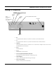
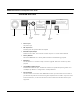

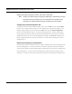
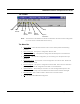
Table Of Contents
- Chapter 1 Introduction
- Features and Benefits
- Features
- Chapter 2 Quick Start
- System Description
- Package Contents
- Installation Steps
- Installation Diagram
- Polarizations on a Grid Antenna
- Chapter 3 Hardware
- Drawings of Components
- Restoring Factory Default Settings on the SPEEDLAN
- Upgrading the Firmware
- Chapter 4 Overview of Configurator
- Installation and Setup
- Toolbar and Menus
- Chapter 5 Configuring SPEEDLAN
- General Setup
- Interface & Advanced Interface Setup
- The Setup Buttons
- Chapter 6 Bridging Setup
- Bridge Setup
- Chapter 7 Setting Up the IP Addresses (IP Host Setup)
- Part I - Quick Overview of IP Addressing
- Part II - Setting Up the IP Address
- Part III - Setting Up NAT
- Chapter 8 IP-Router Setup
- IP Routing Setup
- Chapter 9 SNMP Setup
- SNMP Setup
- Chapter 10 System Access Setup
- System Access Setup
- Chapter 11 SNMP Monitoring

SPEEDLAN Installation and Operation User Guide
Hardware 3-3
SPEEDLAN Back Panel
• Power Input
AC power input
• DC Amp Power
Provides power for optional external amplifier.
• RF Cable Input/Output
Interface for RF cable. The connector used for this port is a reverse TNC bulkhead.
• Factory Default
Places the SPEEDLAN into a factory default mode for troubleshooting purposes.
• Base Boot
Puts the brouter in a mode to accept a firmware upgrade. Not to be used for any other
purpose.
• 10/100Base-T Ethernet Port
Standard RJ-45 Ethernet port. The Ethernet interface is capable of operating either 10 or
100 Mbps. By default it is configured for 10 Mbps Ethernet.
• Serial Number
The silver sticker on the back of the SPEEDLAN is where you will find the serial number of
your brouter. All products are tracked using their respective serial numbers. If you ever need
technical assistance, we will need the serial number to determine the exact build of your
equipment.
Screws
Fan
Power Input
DC Amp
Power
RF Cable
Input/Output
Factory
Base Boot
Switch
Ethernet
PortDefault
Switch
SPEEDLAN
1) This device may not cause
harmful interference.
2) This device must accept
any interference that may
cause undesired operation.
Warning
Do not connect units back-to-back
without RF signal attenuation.