
User's Manual
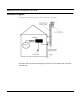
Table Of Contents
- Chapter 1 Introduction
- Features and Benefits
- Features
- Chapter 2 Quick Start
- System Description
- Package Contents
- Installation Steps
- Installation Diagram
- Polarizations on a Grid Antenna
- Chapter 3 Hardware
- Drawings of Components
- Restoring Factory Default Settings on the SPEEDLAN
- Upgrading the Firmware
- Chapter 4 Overview of Configurator
- Installation and Setup
- Toolbar and Menus
- Chapter 5 Configuring SPEEDLAN
- General Setup
- Interface & Advanced Interface Setup
- The Setup Buttons
- Chapter 6 Bridging Setup
- Bridge Setup
- Chapter 7 Setting Up the IP Addresses (IP Host Setup)
- Part I - Quick Overview of IP Addressing
- Part II - Setting Up the IP Address
- Part III - Setting Up NAT
- Chapter 8 IP-Router Setup
- IP Routing Setup
- Chapter 9 SNMP Setup
- SNMP Setup
- Chapter 10 System Access Setup
- System Access Setup
- Chapter 11 SNMP Monitoring

SPEEDLAN Installation and Operation User Guide
Quick Start 2-3
• *Wire zip ties
• *Antenna (specialized upon request)
• *Amplifier (specialized upon request)
* Note:
Items can be purchased separately or as part of an Installation Kit.
Installation Steps
Installation instructions are specific to customers who purchased Installation Kits from Wave
Wireless. To view a diagram of the installation listed below, see Installation Diagram, page 2-7.
The directions below contain installation procedures for the items included in the SPEEDLAN brouter
antenna (and amplifier) kit. If you do not have an item included in the instructions below, contact
Wave Wireless.
If you are having trouble and need a full site installation, contact Wave Wireless Networking for
services and fees.
To install the SPEEDLAN, do the following:
Step 1. Line of Sight
Before installing the antennas and bridges, make sure a clear line of sight exists. Line of sight can be
defined as each antenna being able to clearly see the other antenna or being able to see the remote
locations when viewing from the SPEEDLAN base station location. Be sure to look level with the
center of origin of the transmission (the middle of the antenna). Do the same from the remote
location. Any disruption of the signal path due to trees, buildings or any other obstructions may
cause the link to function improperly. If you see any such obstruction between the two antennas,
move one or both antennas elsewhere.
Step 2. Mount the Antenna
a) On a side building mount, as in the diagram at the end of this section, position the bracket
so there will be at least three feet (one meter) above the roof line of the building where the
pole is attached; this leaves room for the antenna and reduces signal loss from building
reflection.
TIP