
User's Manual
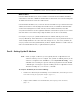
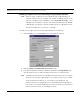
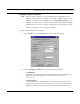
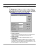
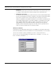
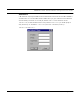
Table Of Contents
- Chapter 1 Introduction
- Features and Benefits
- Transparent Ethernet Bridging with Advanced Filtering for Security and Network Reliability
- IP Routing with Advanced Filtering for Security
- SNMP Management
- SNMP Features
- SNMP Management
- IP-Router Features
- Encryption Features (Add-on Option)
- Wireless Multipoint Protocol
- Additional Functionality for SPEEDLAN 4100 & 4200
- Features
- Chapter 2 Quick Start
- System Description
- Package Contents
- Installation Steps
- Installation Diagram
- Polarizations on a Grid Antenna
- Chapter 3 Hardware
- Upgrading the Firmware
- Chapter 4 Overview of Configurator
- Installation and Setup
- Toolbar and Menus
- Chapter 5 Configuring SPEEDLAN 4100 & 4200
- General Setup
- Interface & Advanced Interface Setup
- The Setup Buttons
- Chapter 6 Bridging Setup
- Bridge Setup
- Chapter 7 Setting Up the IP Addresses (IP Host Setup)
- Part I - Quick Overview of IP Addressing
- Part II - Setting Up the IP Address
- Chapter 8 IP-Router Setup
- IP Routing Setup
- Chapter 9 SNMP Setup
- SNMP Setup
- Chapter 10 System Access Setup
- System Access Setup
- Chapter 11 SNMP Monitoring
- Remote Statistics
- Interface Monitor
- Ethernet-like Interface Monitor
- Campus PRC Station Entries
- 11Mb RF Interface
- SNMP Monitor
- IP Monitor
- IP/TCP/UDP Monitor
- ICMP Monitor
- Chapter 12 Tables
- System Information
- Bridge Learn Table
- IP ARP Table
- IP Route Table
- IP/TCP Connection Table
- IP/UDP Listener Table
- Local IP-Address Table
- Chapter 13 Analyzing Wireless Equipment
- Select Another Device
- Analysis Polling Interval
- Wireless Link Test
- Antenna Alignment
- Glossary for Standard Data Communications
- Glossary for Standard Data Communications
- Appendix Protocols & Ethernet Addresses
- Common Ethernet Protocols
- Common Ethernet Vendor Addresses
- Common Ethernet Multicast Addresses
- Common Ethernet Broadcast Addresses

SPEEDLAN 4100 & 4200 Installation and Operation User Guide
Setting Up the IP Addresses (IP Host Setup) 7-13
Note: For more information, see Subnetting a Network, page 7-5. Once the packet has trav-
eled to the appropriate network, it goes through a masking process. A subnet mask is
composed of zeros (0s) and ones (1s). This tells the router which addresses to look
under and which ones not to look under. Therefore, subnet masking allows the router
to transfer the packet traffic more quickly than a network without a subnet. Again, this
address is obtained from the network administrator, IP host, or host provider.
• Default Router IP
If you have an established network, use the IP address for the router already set up for
that network. If you do not have an established network, leave this entry blank.
• Default TTL
This information should already be entered. The IP host on the Internet will send out
each packet with a default "Time to Live" parameter. If you want to override the factory
default of 64 attempts, you can specify your new default here. This parameter should
not be changed unless you are very familiar with IP functionality and how the Time to
Live parameter will affect how packets are treated by your network, as well as the net-
work to which you are bridged (or routed).
Note: Click Select to view the IP Mask List. Select the appropriate IP Mask and click OK.
3 After you have finished entering the appropriate information, click OK.
4 Now save the changes to the brouter. From the File menu, choose Save Config.
5 A message box appears informing you that the information will be saved to the brouter (i.e.,
128.104.22.4). Click Yes.
6 The Configurator confirms that the configuration has been saved. Click OK. The computer
will reboot at this point.
Note: You are finished with this section.