
User's Manual
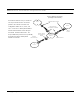

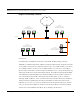
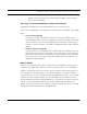
Table Of Contents
- Chapter 1 Introduction
- Features and Benefits
- Transparent Ethernet Bridging with Advanced Filtering for Security and Network Reliability
- IP Routing with Advanced Filtering for Security
- SNMP Management
- SNMP Features
- SNMP Management
- IP-Router Features
- Encryption Features (Add-on Option)
- Wireless Multipoint Protocol
- Additional Functionality for SPEEDLAN 4100 & 4200
- Features
- Chapter 2 Quick Start
- System Description
- Package Contents
- Installation Steps
- Installation Diagram
- Polarizations on a Grid Antenna
- Chapter 3 Hardware
- Upgrading the Firmware
- Chapter 4 Overview of Configurator
- Installation and Setup
- Toolbar and Menus
- Chapter 5 Configuring SPEEDLAN 4100 & 4200
- General Setup
- Interface & Advanced Interface Setup
- The Setup Buttons
- Chapter 6 Bridging Setup
- Bridge Setup
- Chapter 7 Setting Up the IP Addresses (IP Host Setup)
- Part I - Quick Overview of IP Addressing
- Part II - Setting Up the IP Address
- Chapter 8 IP-Router Setup
- IP Routing Setup
- Chapter 9 SNMP Setup
- SNMP Setup
- Chapter 10 System Access Setup
- System Access Setup
- Chapter 11 SNMP Monitoring
- Remote Statistics
- Interface Monitor
- Ethernet-like Interface Monitor
- Campus PRC Station Entries
- 11Mb RF Interface
- SNMP Monitor
- IP Monitor
- IP/TCP/UDP Monitor
- ICMP Monitor
- Chapter 12 Tables
- System Information
- Bridge Learn Table
- IP ARP Table
- IP Route Table
- IP/TCP Connection Table
- IP/UDP Listener Table
- Local IP-Address Table
- Chapter 13 Analyzing Wireless Equipment
- Select Another Device
- Analysis Polling Interval
- Wireless Link Test
- Antenna Alignment
- Glossary for Standard Data Communications
- Glossary for Standard Data Communications
- Appendix Protocols & Ethernet Addresses
- Common Ethernet Protocols
- Common Ethernet Vendor Addresses
- Common Ethernet Multicast Addresses
- Common Ethernet Broadcast Addresses

SPEEDLAN 4100 & 4200 Installation and Operation User Guide
Bridging Setup 6-9
Generic Ethernet Tunneling
(Through an IP Network)
LAN A
LAN C
LAN B
Internet or
Campus IP
Network
Standard Ethernet Packet
Ethernet Packet
Encapsulated in IP/UDP
Ethernet Packet
Encapsulated in
IP/UDP
Standard
Ethernet Packet
Local
Interface
Remote Interface
The three brouters are set up to tunnel one
or more protocols and each is a tunnel
partner to the other two brouters. This
configuration allows LAN A, LAN B, and
LAN C to become a virtual private Ethernet
network with the Internet as the transport
mechanism for data between them. The
encapsulated data packets can be optionally
encrypted to make the virtual private
network more secure.