
User's Manual
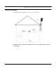
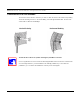
Table Of Contents
- Chapter 1 Introduction
- Features and Benefits
- Transparent Ethernet Bridging with Advanced Filtering for Security and Network Reliability
- IP Routing with Advanced Filtering for Security
- SNMP Management
- SNMP Features
- SNMP Management
- IP-Router Features
- Encryption Features (Add-on Option)
- Wireless Multipoint Protocol
- Additional Functionality for SPEEDLAN 4100 & 4200
- Features
- Chapter 2 Quick Start
- System Description
- Package Contents
- Installation Steps
- Installation Diagram
- Polarizations on a Grid Antenna
- Chapter 3 Hardware
- Upgrading the Firmware
- Chapter 4 Overview of Configurator
- Installation and Setup
- Toolbar and Menus
- Chapter 5 Configuring SPEEDLAN 4100 & 4200
- General Setup
- Interface & Advanced Interface Setup
- The Setup Buttons
- Chapter 6 Bridging Setup
- Bridge Setup
- Chapter 7 Setting Up the IP Addresses (IP Host Setup)
- Part I - Quick Overview of IP Addressing
- Part II - Setting Up the IP Address
- Chapter 8 IP-Router Setup
- IP Routing Setup
- Chapter 9 SNMP Setup
- SNMP Setup
- Chapter 10 System Access Setup
- System Access Setup
- Chapter 11 SNMP Monitoring
- Remote Statistics
- Interface Monitor
- Ethernet-like Interface Monitor
- Campus PRC Station Entries
- 11Mb RF Interface
- SNMP Monitor
- IP Monitor
- IP/TCP/UDP Monitor
- ICMP Monitor
- Chapter 12 Tables
- System Information
- Bridge Learn Table
- IP ARP Table
- IP Route Table
- IP/TCP Connection Table
- IP/UDP Listener Table
- Local IP-Address Table
- Chapter 13 Analyzing Wireless Equipment
- Select Another Device
- Analysis Polling Interval
- Wireless Link Test
- Antenna Alignment
- Glossary for Standard Data Communications
- Glossary for Standard Data Communications
- Appendix Protocols & Ethernet Addresses
- Common Ethernet Protocols
- Common Ethernet Vendor Addresses
- Common Ethernet Multicast Addresses
- Common Ethernet Broadcast Addresses

SPEEDLAN 4100 & 4200 Installation and Operation User Guide
2-4 Quick Start
Step 2. Mounting the Antenna
Follow the instructions below to mount the antenna.
Note: You can use a 24db grid antenna to achieve a link as long as the remote brouter can
hear it.
a) On a side-building mount, position the bracket so there will be at least three feet (one
meter) above the roof line where the pole is attached. This enables room for the antenna
and reduces signal loss from building reflection.
Note: It is not recommended to mount the antenna onto any unstable object. For more infor-
mation on antennas, see Polarizations on a Grid Antenna, page 2-9.
b) Allow for as much space between the wall brackets as possible while maintaining the
appropriate antenna height. For extended poles, additional wall brackets may be necessary.
c) Assemble the antenna and mount it to the pole using the included U-bolt antenna mounting
hardware. For a semi-parabolic grid type antenna, align the grid to run parallel with the
grid on the tip of the antenna horn. Preferably, the grid should be horizontal (or parallel to
the ground). Make sure all bolts and screws are fastened tightly.
d) Fasten the pole to the brackets. Position the antenna, point it in the appropriate direction,
and tighten the screws. Then, aim the antenna so it is pointed toward the receiving antenna
on the other building. The radio signal radiates from the end of antenna like a wide-
beamed flashlight. For optimal performance, you may need to test your link using both
polarities. This configuration option varies with each location, as well as RF signals that may
be present in the area.