
User Manual


SPEEDCOM SC5800 User Manual
32
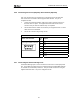
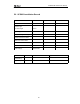
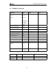
4.4.1 INTERCONNECTION CABLE WIRING DESCRIPTION
18
TOP VIEW (LOCKING
TAB UNDERNEATH)
RJ-45 PLUG
Pin DTE (on
INDOOR
UNIT)
DCE (on
OUTDOOR UNIT)
1 TxD+ RxD-+
2 TxD- RxD-+
3 RxD+ TxD+
4† TxC+ RxC+
5† TxC- RxC-
6 RxD- TxD-
7† RxC+ TxC+
8† RxC- TxC-
NOTES
• † Version 2 releases of the hardware (indoor and outdoor units) cannot be used
interchangeably. For version 2 IU & OU hardware, use of TxC+, TxC-, RxC+, RxC- falls
away and only two (2) twisted pairs are required.
• The important point is that the interconnect cable is wired as a standard 1-to-1 Ethernet
patch cable.
• Pairs 4/5 and 7/8 are not required or used on Version 2 products.